
Solar-Powered Arduino-Controlled Stepper Motor with Light Sensing and Blinker Indication
View and Edit Project In Cirkit Designer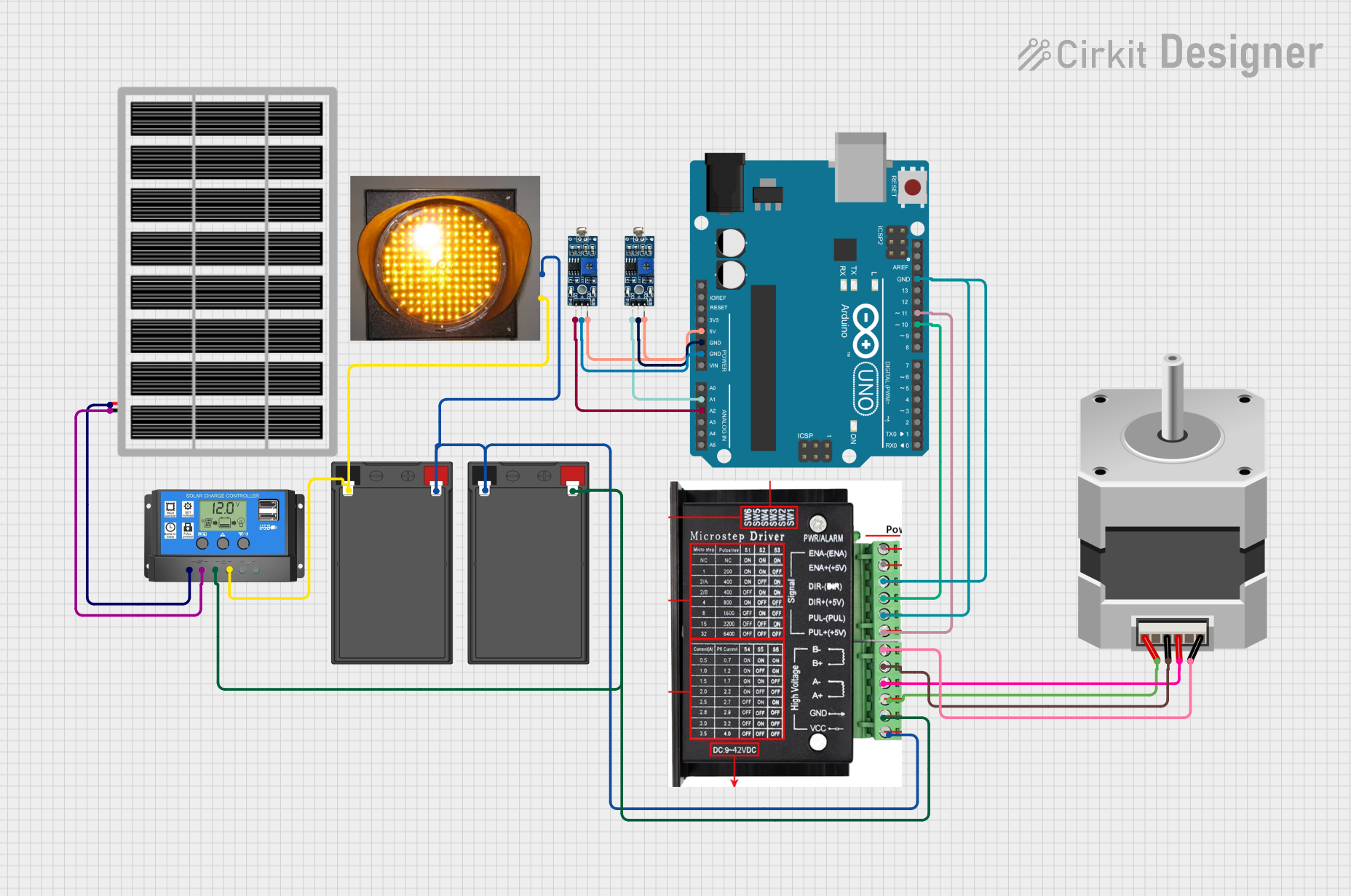
Solar-Powered Stepper Motor Control Circuit Documentation
Summary
This circuit is designed to control a bipolar stepper motor using an Arduino UNO microcontroller. The power for the circuit is supplied by a solar panel, which charges a battery through a solar charge controller. The battery then provides a stable power supply to the stepper motor driver and the Arduino UNO. The circuit also includes two LDR (Light Dependent Resistor) modules that interface with the Arduino UNO to potentially adjust the motor control based on light conditions. A blinker is included for indication purposes.
Component List
Solar Panel
- Description: A photovoltaic panel that converts sunlight into electrical energy.
- Purpose: To provide a renewable energy source for charging the battery.
Battery (x2)
- Description: Energy storage devices that provide power to the circuit.
- Purpose: To store electrical energy from the solar panel and supply power to the circuit when sunlight is insufficient.
Solar Charge Controller
- Description: A device that controls the charging of the battery from the solar panel and protects against overcharging.
- Purpose: To manage the power flow from the solar panel to the battery and the load.
Blinker
- Description: An indicator device that blinks at a regular interval.
- Purpose: To provide a visual indication of the circuit's operational status.
LDR Module 3 pin (x2)
- Description: A sensor module with a light-dependent resistor that outputs a digital signal.
- Purpose: To detect light levels and provide input to the Arduino UNO for controlling the stepper motor based on ambient light.
Arduino UNO
- Description: A microcontroller board based on the ATmega328P.
- Purpose: To control the stepper motor driver based on inputs from the LDR modules and to manage the overall functionality of the circuit.
Stepper Motor Driver
- Description: A device that drives a stepper motor by providing the necessary current and direction signals.
- Purpose: To control the stepper motor's steps and direction as commanded by the Arduino UNO.
Stepper Motor (Bipolar)
- Description: A type of stepper motor with two coils that can be driven with current in either direction.
- Purpose: To perform mechanical movements with precision as controlled by the stepper motor driver.
Wiring Details
Solar Panel
- VCC: Connected to the Solar Charge Controller's Solar Cell +.
- GND: Connected to the Solar Charge Controller's Solar Cell -.
Battery
- +: One battery's positive terminal is connected to the Solar Charge Controller's Battery + and the stepper motor driver's VCC. The other battery's positive terminal is connected to the blinker's Vcc +12v.
- -: One battery's negative terminal is connected to the Solar Charge Controller's Battery - and the blinker's Gnd. The other battery's negative terminal is connected to the stepper motor driver's GNC.
Solar Charge Controller
- Solar Cell +: Connected to the Solar Panel's VCC.
- Solar Cell -: Connected to the Solar Panel's GND.
- Battery +: Connected to one battery's + terminal.
- Battery -: Connected to the other battery's - terminal.
- Load +: Not specified in the net list.
- Load -: Not specified in the net list.
Blinker
- Vcc +12v: Connected to one battery's + terminal.
- Gnd: Connected to the other battery's - terminal.
LDR Module 3 pin
- VCC: Both modules' VCC pins are connected to the Arduino UNO's 5V pin.
- GND: Both modules' GND pins are connected to the Arduino UNO's GND pin.
- DO: One module's DO pin is connected to the Arduino UNO's A1 pin, and the other module's DO pin is connected to the Arduino UNO's A2 pin.
Arduino UNO
- 5V: Connected to both LDR modules' VCC pins.
- GND: Connected to both LDR modules' GND pins, the stepper motor driver's PUL--, and DIR.
- A1: Connected to one LDR module's DO pin.
- A2: Connected to the other LDR module's DO pin.
- D10: Connected to the stepper motor driver's DIR(+5V).
- D11: Connected to the stepper motor driver's PUL+.
Stepper Motor Driver
- GNC: Connected to one battery's - terminal.
- VCC: Connected to the other battery's + terminal.
- A+: Connected to the Stepper Motor's A pin.
- A--: Connected to the Stepper Motor's B pin.
- B+: Connected to the Stepper Motor's C pin.
- B--: Connected to the Stepper Motor's D pin.
- ENA-: Not specified in the net list.
- ENA+: Not specified in the net list.
- DIR: Connected to the Arduino UNO's GND.
- DIR(+5V): Connected to the Arduino UNO's D10.
- PUL--: Connected to the Arduino UNO's GND.
- PUL+: Connected to the Arduino UNO's D11.
Stepper Motor (Bipolar)
- A: Connected to the stepper motor driver's A+.
- B: Connected to the stepper motor driver's A--.
- C: Connected to the stepper motor driver's B+.
- D: Connected to the stepper motor driver's B--.
Documented Code
Arduino UNO (sketch.ino)
void setup() {
  // put your setup code here, to run once:

}

void loop() {
  // put your main code here, to run repeatedly:

}
Arduino UNO (documentation.txt)
(No additional documentation provided)
This documentation provides an overview of the circuit components, their wiring, and the initial code for the Arduino UNO. Further development of the code is required to implement the control logic for the stepper motor based on the LDR inputs.