
ATMEGA328-Based Automated Water Quality Monitoring System with Motor-Driven Water Pump
View and Edit Project In Cirkit Designer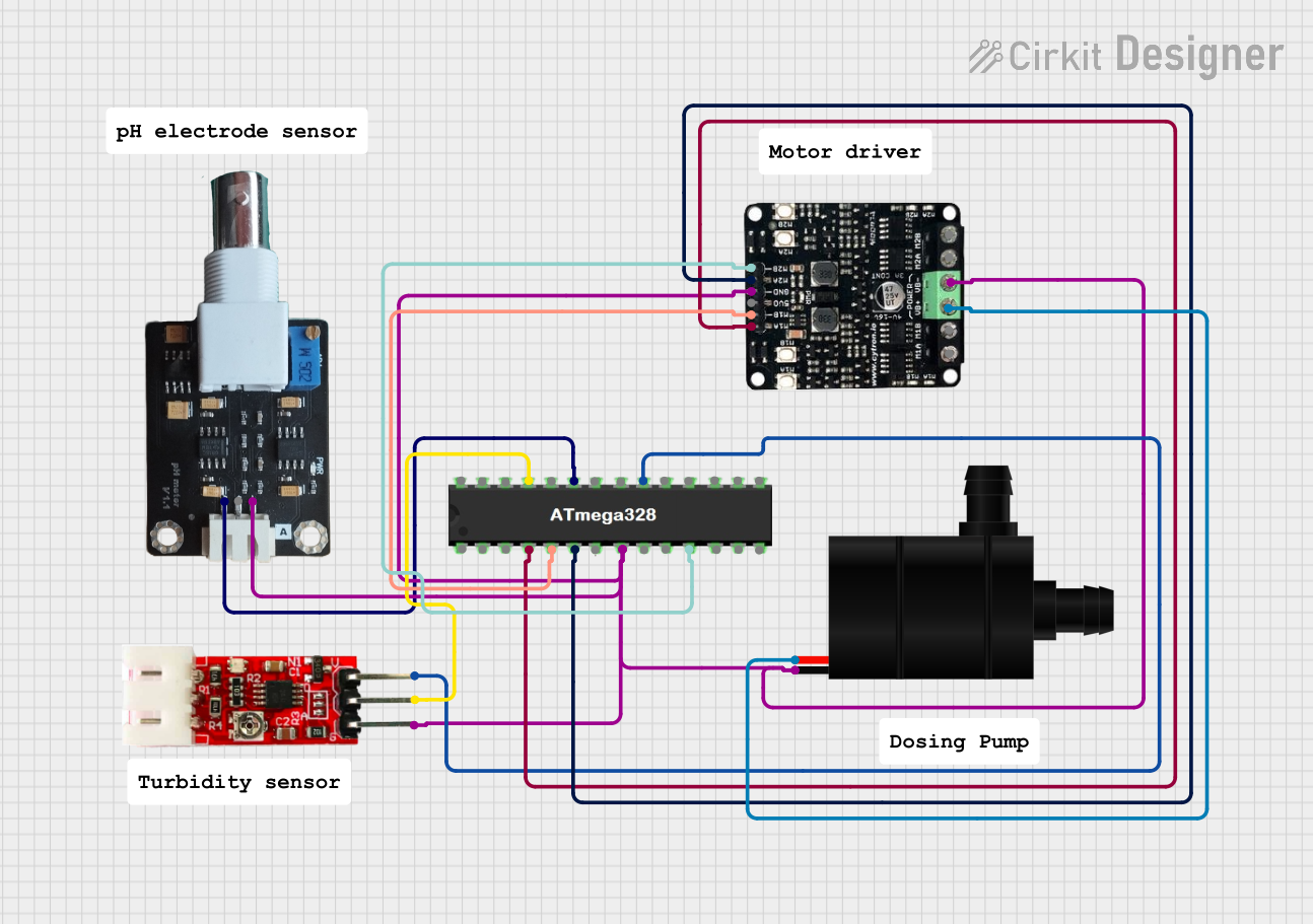
Circuit Documentation
Summary
This document provides a detailed overview of a circuit designed to control a water pump and monitor water quality using a turbidity module and a pH meter. The circuit is controlled by an ATMEGA328 microcontroller, which interfaces with a motor driver to control the water pump and reads data from the turbidity module and pH meter.
Component List
Water Pump
- Pins: VCC, GND
- Description: A pump used to move water.
- Purpose in Circuit: Controlled by the motor driver to manage water flow.
Motor Driver
- Pins: VB+, VB-, M1A, M1B, M2A, M2B, 5V, GND
- Description: A driver used to control motors.
- Purpose in Circuit: Controls the water pump based on signals from the microcontroller.
Turbidity Module
- Pins: VCC, GND, OUT
- Description: A sensor used to measure the turbidity (cloudiness) of water.
- Purpose in Circuit: Provides turbidity data to the microcontroller.
pH Meter V1.1
- Pins: DATA, VCC, GND
- Description: A sensor used to measure the pH level of water.
- Purpose in Circuit: Provides pH data to the microcontroller.
ATMEGA328
- Pins: RESET, D0, D1, D2, D3, D4, VCC, GND, CRYSTAL, D5, D6, D7, D8, D9, D10, D11, D12, D13, AREF, A0, A1, A2, A3, A4, A5
- Description: A microcontroller used to control the circuit.
- Purpose in Circuit: Reads data from sensors and controls the motor driver.
Wiring Details
Water Pump
- VCC is connected to VB+ of the Motor Driver.
- GND is connected to the common ground shared with the ATMEGA328, Motor Driver, pH Meter, and Turbidity Module.
Motor Driver
- VB+ is connected to VCC of the Water Pump.
- VB- is connected to the common ground.
- M1A is connected to D2 of the ATMEGA328.
- M1B is connected to D3 of the ATMEGA328.
- M2A is connected to D4 of the ATMEGA328.
- M2B is connected to D5 of the ATMEGA328.
- 5V is not connected in this circuit.
- GND is connected to the common ground.
Turbidity Module
- VCC is connected to VCC of the ATMEGA328.
- GND is connected to the common ground.
- OUT is connected to A2 of the ATMEGA328.
pH Meter V1.1
- DATA is connected to A0 of the ATMEGA328.
- VCC is not connected in this circuit.
- GND is connected to the common ground.
ATMEGA328
- A0 is connected to DATA of the pH Meter.
- A2 is connected to OUT of the Turbidity Module.
- D2 is connected to M1A of the Motor Driver.
- D3 is connected to M1B of the Motor Driver.
- D4 is connected to M2A of the Motor Driver.
- D5 is connected to M2B of the Motor Driver.
- VCC is connected to VCC of the Turbidity Module.
- GND is connected to the common ground shared with the Motor Driver, pH Meter, Water Pump, and Turbidity Module.
Code
No code is provided for this circuit.
This document provides a comprehensive overview of the circuit, including a summary, component list, wiring details, and code documentation. The circuit is designed to control a water pump and monitor water quality using a turbidity module and a pH meter, all controlled by an ATMEGA328 microcontroller.