
Wi-Fi Controlled Vibration and Piezo Sensor System with ESP8266 and Relay
View and Edit Project In Cirkit Designer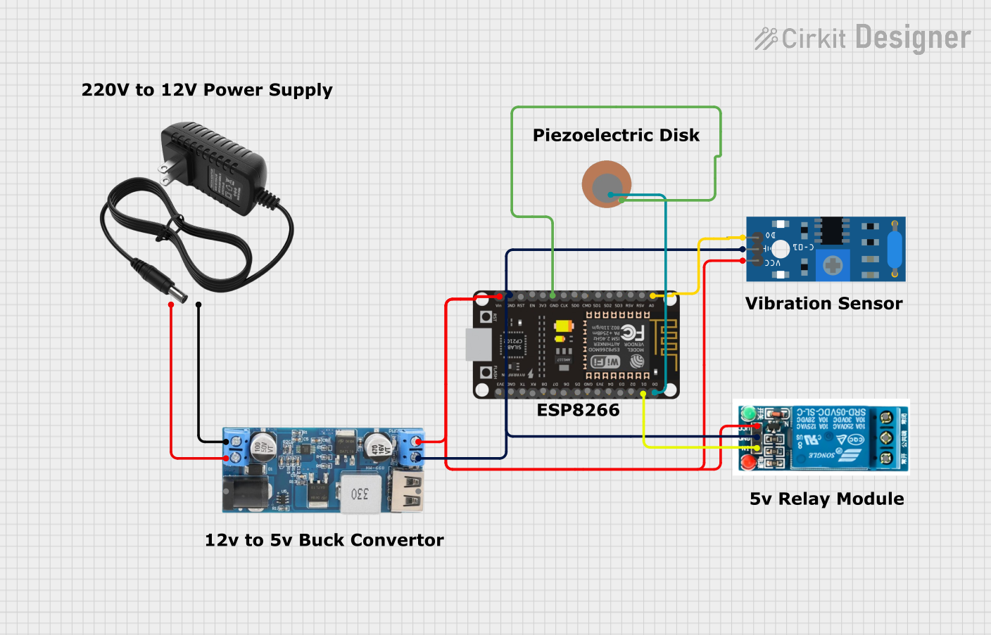
Circuit Documentation
Summary
This circuit involves a variety of components including a 5V relay, a piezo sensor, an SW-420 vibration sensor, a 12V to 5V step-down power converter, a 12V power supply, and an ESP8266 NodeMCU microcontroller. The circuit is designed to detect vibrations using the SW-420 sensor and the piezo sensor, and then trigger a relay based on the detected signals. The ESP8266 NodeMCU microcontroller is used to process the sensor data and control the relay.
Component List
5V Relay
- Description: A relay that operates at 5V.
- Pins: Normally Open, Common terminal, Normally Closed, In, GND, VCC
Piezo Sensor
- Description: A sensor that detects vibrations.
- Pins: +, -
SW-420 Vibration Sensor
- Description: A vibration sensor that provides a digital output.
- Pins: vcc, Ground, Digital output
12V to 5V Step Down Power Converter
- Description: A power converter that steps down 12V to 5V.
- Pins: VIN 9v-36v, VIN+, VIN-, USB OUTPUT 5V, 5v OUTPUT, GND
12V Power Supply
- Description: A power supply that provides 12V.
- Pins: +, -
ESP8266 NodeMCU
- Description: A microcontroller with Wi-Fi capabilities.
- Pins: D0, D1, D2, D3, D4, 3V3, GND, D5, D6, D7, D8, RX, TX, A0, RSV, SD3, SD2, SD1, CMD, SD0, CLK, EN, RST, VIN
Wiring Details
5V Relay
- In is connected to D1 of the ESP8266 NodeMCU.
- GND is connected to GND of the ESP8266 NodeMCU, the SW-420 Vibration Sensor, and the 12V to 5V Step Down Power Converter.
- VCC is connected to VIN of the ESP8266 NodeMCU, vcc of the SW-420 Vibration Sensor, and 5v OUTPUT of the 12V to 5V Step Down Power Converter.
Piezo Sensor
- + is connected to D0 of the ESP8266 NodeMCU.
- - is connected to GND of the ESP8266 NodeMCU.
SW-420 Vibration Sensor
- Digital output is connected to A0 of the ESP8266 NodeMCU.
- Ground is connected to GND of the ESP8266 NodeMCU, the 12V to 5V Step Down Power Converter, and the 5V Relay.
- vcc is connected to VIN of the ESP8266 NodeMCU, 5v OUTPUT of the 12V to 5V Step Down Power Converter, and VCC of the 5V Relay.
12V to 5V Step Down Power Converter
- VIN+ is connected to + of the 12V Power Supply.
- VIN- is connected to - of the 12V Power Supply.
- GND is connected to GND of the ESP8266 NodeMCU, the SW-420 Vibration Sensor, and the 5V Relay.
- 5v OUTPUT is connected to VIN of the ESP8266 NodeMCU, vcc of the SW-420 Vibration Sensor, and VCC of the 5V Relay.
12V Power Supply
- + is connected to VIN+ of the 12V to 5V Step Down Power Converter.
- - is connected to VIN- of the 12V to 5V Step Down Power Converter.
ESP8266 NodeMCU
- D0 is connected to + of the Piezo Sensor.
- D1 is connected to In of the 5V Relay.
- A0 is connected to Digital output of the SW-420 Vibration Sensor.
- GND is connected to GND of the Piezo Sensor, the SW-420 Vibration Sensor, and the 12V to 5V Step Down Power Converter.
- VIN is connected to 5v OUTPUT of the 12V to 5V Step Down Power Converter, vcc of the SW-420 Vibration Sensor, and VCC of the 5V Relay.
Code
No code is provided for this circuit.