
ESP32-CAM and 74HC595 Controlled LED Array with Battery Power
View and Edit Project In Cirkit Designer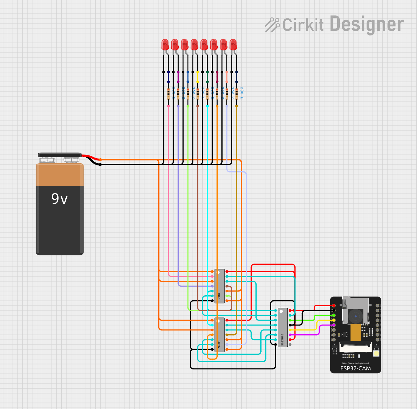
Circuit Documentation
Summary
This circuit involves an ESP32-CAM microcontroller, a 74HC595 shift register, multiple 4066 analog switches, resistors, and LEDs. The ESP32-CAM controls the shift register, which in turn controls the analog switches. The analog switches are used to control the LEDs through resistors. The circuit is powered by a 9V battery.
Component List
74HC595 Shift Register
- Description: 8-bit serial-in, serial or parallel-out shift register with output latches.
- Pins: Q0-Q7, DS (DATA), OE (Enable), ST_CP (RCLK), SH_CP (SRCLK), MR (SRCLR), Q7' (QH), GND, VCC
ESP32-CAM
- Description: A low-cost microcontroller with integrated Wi-Fi and Bluetooth, featuring a camera module.
- Pins: 5V, GND, IO0, IO2, IO4, IO12, IO13, IO14, IO15, IO16, VOT, VOR, VCC, 3V3
4066 Analog Switch
- Description: Quad bilateral switch.
- Pins: X1 (Input 1), Y1 (Output 1), X2 (Input 2), Y2 (Output 2), A1 (Control A), A2 (Control B), A3 (Control C), A4 (Control D), X3 (Output 3), Y3 (Input 3), X4 (Output 4), Y4 (Input 4), GND, VCC
9V Battery
- Description: Power source for the circuit.
- Pins: +, -
Resistor
- Description: 200 Ohms resistor.
- Pins: pin1, pin2
LED: Two Pin (red)
- Description: Red LED.
- Pins: cathode, anode
Wiring Details
74HC595 Shift Register
- Q0: Connected to A1 (Control A) of 4066
- Q1: Connected to A2 (Control B) of 4066
- Q2: Connected to A3 (Control C) of 4066
- Q3: Connected to A4 (Control D) of 4066
- Q4: Connected to A1 (Control A) of another 4066
- Q5: Connected to A2 (Control B) of another 4066
- Q6: Connected to A3 (Control C) of another 4066
- Q7: Connected to A4 (Control D) of another 4066
- DS (DATA): Connected to IO12 of ESP32-CAM
- OE (Enable): Connected to GND
- ST_CP (RCLK): Connected to IO13 of ESP32-CAM
- SH_CP (SRCLK): Connected to IO15 of ESP32-CAM
- MR (SRCLR): Connected to 5V
- GND: Connected to GND
- VCC: Connected to 5V
ESP32-CAM
- 5V: Connected to 5V
- GND: Connected to GND
- IO12: Connected to DS (DATA) of 74HC595
- IO13: Connected to ST_CP (RCLK) of 74HC595
- IO15: Connected to SH_CP (SRCLK) of 74HC595
4066 Analog Switch
- A1 (Control A): Connected to Q0 of 74HC595
- A2 (Control B): Connected to Q1 of 74HC595
- A3 (Control C): Connected to Q2 of 74HC595
- A4 (Control D): Connected to Q3 of 74HC595
- X1 (Input 1): Connected to 9V Battery +
- Y1 (Output 1): Connected to pin2 of Resistor
- X2 (Input 2): Connected to 9V Battery +
- Y2 (Output 2): Connected to pin2 of Resistor
- X3 (Output 3): Connected to pin2 of Resistor
- Y3 (Input 3): Connected to 9V Battery +
- X4 (Output 4): Connected to pin2 of Resistor
- Y4 (Input 4): Connected to 9V Battery +
- GND: Connected to GND
- VCC: Connected to 5V
9V Battery
- +: Connected to X1, X2, Y3, Y4 of 4066
- -: Connected to cathode of all LEDs
Resistor
- pin1: Connected to anode of LED
- pin2: Connected to Y1, Y2, X3, X4 of 4066
LED: Two Pin (red)
- cathode: Connected to 9V Battery -
- anode: Connected to pin1 of Resistor
Code Documentation
sketch.ino
int latchPin = 13;  // ST_CP
int clockPin = 15;  // SH_CP
int dataPin = 12;   // DS

void setup() {
  pinMode(dataPin, OUTPUT);
  pinMode(clockPin, OUTPUT);
  pinMode(latchPin, OUTPUT);

  Serial.begin(9600);
  Serial.print("Start...");
  setSwitch(B00000000);
}

void setSwitch(byte status) {
  digitalWrite(latchPin, LOW);
  shiftOut(dataPin, clockPin, MSBFIRST, status);
  digitalWrite(latchPin, HIGH);
}

void loop() {
  setSwitch(B01001000);
  delay(1000);
  setSwitch(B10110111);
  delay(1000);
}
This code initializes the ESP32-CAM to control the 74HC595 shift register. The setSwitch function sets the state of the shift register, which in turn controls the analog switches. The loop function alternates the state of the switches every second.