Cirkit Designer
Your all-in-one circuit design IDE
Home /
Project Documentation
ESP8266-Controlled Wireless EV Charging System with RFID Authentication
Circuit Documentation
Summary
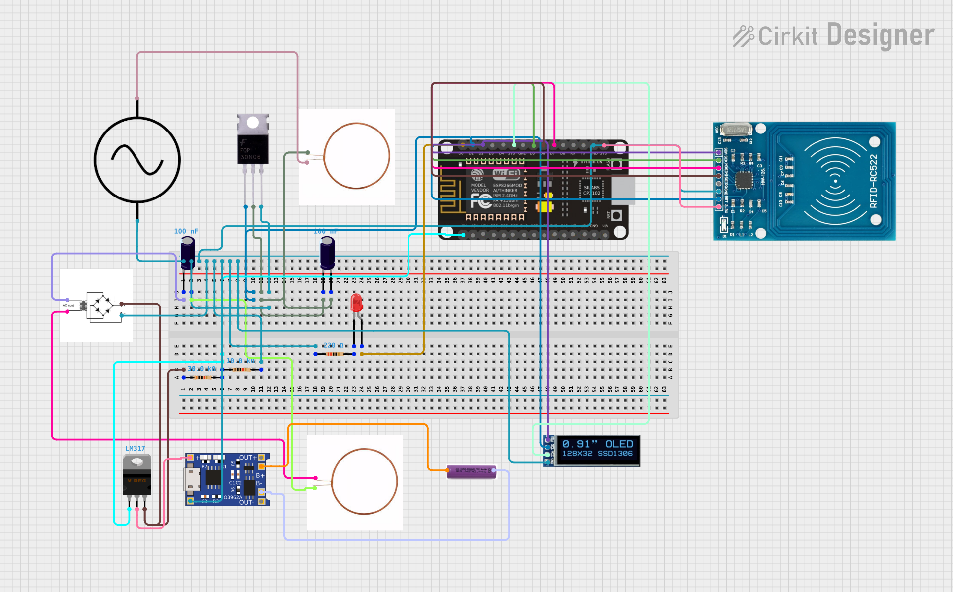
The circuit in question appears to be a wireless charging system with a microcontroller-based control unit. The system includes a power supply, a bridge rectifier for AC to DC conversion, a voltage regulator, a charging module, and a battery. It also features a MOSFET for controlling the charging process, an OLED display for user interface, and an RFID reader for authentication or control purposes. The microcontroller used is an ESP8266 NodeMCU, which manages the charging logic, display output, and RFID communication.
Component List
Mosfet
- Description: A semiconductor device used to switch or amplify electronic signals.
- Pins: Gate, Drain, Source
Copper Coil
- Description: Used in inductive charging to create a magnetic field for wireless power transfer.
- Pins: -ve, +ve
AC Supply
- Description: Provides alternating current power to the circuit.
- Pins: +ve, -ve
ESP8266 NodeMCU
- Description: A microcontroller with Wi-Fi capabilities for IoT projects.
- Pins: D0, D1, D2, D3, D4, 3V3, GND, D5, D6, D7, D8, RX, TX, A0, RSV, SD3, SD2, SD1, CMD, SD0, CLK, EN, RST, VIN
Electrolytic Capacitor
- Description: A polarized capacitor with a larger capacitance, used for filtering or energy storage.
- Pins: -, +
- Properties: Capacitance: 1e-7 Farads
Bridge Rectifier
- Description: Converts AC to DC in the circuit.
- Pins: AC input +, AC input -, +, -
LM317 Voltage Regulator
- Description: An adjustable voltage regulator to maintain a constant output voltage.
- Pins: Adj, V_out, V_in
TP4056
- Description: A lithium battery charging module with battery protection.
- Pins: OUT-, B-, B+, OUT+, IN-, IN+
3.7v Battery
- Description: Provides power storage for the circuit.
- Pins: +, -
Resistor
- Description: A passive two-terminal electrical component that implements electrical resistance.
- Properties: Resistance: Various values in Ohms
LED: Two Pin (red)
- Description: A red light-emitting diode used as an indicator.
- Pins: cathode, anode
OLED Display 128x32
- Description: A small display for visual output.
- Pins: SDA, SCL, VCC, GND
RFID-RC522
- Description: An RFID reader/writer module.
- Pins: VCC (3.3V), RST, GND, IRQ, MISO, MOSI, SCK, SDA
Wiring Details
Mosfet
- Gate connected to ESP8266 NodeMCU D1
- Drain connected to Copper Coil +ve and Electrolytic Capacitor -
- Source connected to Resistor pin2, AC Supply -ve, RFID-RC522 GND, ESP8266 NodeMCU GND, Bridge Rectifier -, TP4056 IN-, OLED Display GND
Copper Coil (Wireless Charging Coil)
- -ve connected to Electrolytic Capacitor +
- +ve connected to AC Supply +ve
AC Supply
- +ve connected to Copper Coil +ve
- -ve connected to Mosfet Source
ESP8266 NodeMCU
- D0 connected to LED anode
- D1 connected to Mosfet Gate
- D2 connected to OLED Display SDA and RFID-RC522 SDA
- D3 (Not connected)
- D4 (Not connected)
- 3V3 connected to OLED Display VCC and RFID-RC522 VCC (3.3V)
- GND connected to Mosfet Source
- A0 connected to LM317 Voltage Regulator Adj and Resistor pin1
- Other pins (Not connected)
Electrolytic Capacitor
- connected to Bridge Rectifier AC input +
- connected to Copper Coil -ve
Bridge Rectifier
- AC input + connected to Electrolytic Capacitor -
- AC input - connected to Copper Coil -ve
- connected to LM317 Voltage Regulator V_in and Resistor pin1
- connected to Mosfet Source
LM317 Voltage Regulator
- Adj connected to ESP8266 NodeMCU A0 and Resistor pin1
- V_out connected to TP4056 IN+
- V_in connected to Bridge Rectifier + and Resistor pin1
TP4056
- IN+ connected to LM317 Voltage Regulator V_out
- IN- connected to Mosfet Source
- B+ connected to 3.7v Battery +
- B- connected to 3.7v Battery -
- OUT+ (Not connected)
- OUT- (Not connected)
3.7v Battery
- connected to TP4056 B+
- connected to TP4056 B-
Resistor
- Various resistors are used in the circuit with connections to the LM317 Voltage Regulator, Mosfet, and LED.
LED: Two Pin (red)
- anode connected to ESP8266 NodeMCU D0
- cathode connected to Resistor pin2
OLED Display 128x32
- SDA connected to ESP8266 NodeMCU D2 and RFID-RC522 SDA
- SCL (Not connected)
- VCC connected to ESP8266 NodeMCU 3V3
- GND connected to Mosfet Source
RFID-RC522
- VCC (3.3V) connected to ESP8266 NodeMCU 3V3
- RST connected to Mosfet Gate
- GND connected to Mosfet Source
- IRQ (Not connected)
- MISO connected to ESP8266 NodeMCU D6
- MOSI connected to ESP8266 NodeMCU D7
- SCK connected to ESP8266 NodeMCU D5
- SDA connected to ESP8266 NodeMCU D2 and OLED Display SDA
Documented Code
ESP8266 NodeMCU Code (sketch.ino)
#include <Wire.h>
#include <Adafruit_GFX.h>
#include <Adafruit_SSD1306.h>

// Define display dimensions
#define SCREEN_WIDTH 128
#define SCREEN_HEIGHT 32
#define OLED_RESET -1

Adafruit_SSD1306 display(SCREEN_WIDTH, SCREEN_HEIGHT, &Wire, OLED_RESET);

const int mosfetPin = 5;  // GPIO5
const int ledPin = 16;    // GPIO16

void setup() {
  Serial.begin(115200);  // Start serial communication

  if(!display.begin(SSD1306_SWITCHCAPVCC, 0x3C)) {
    Serial.println(F("SSD1306 allocation failed"));
    for(;;);  // Infinite loop to halt if display allocation fails
  }
  display.display();
  delay(2000);

  pinMode(mosfetPin, OUTPUT);  // Set MOSFET control pin as output
  pinMode(ledPin, OUTPUT);     // Set LED pin as output

  digitalWrite(mosfetPin, LOW);  // Start with MOSFET off
  digitalWrite(ledPin, LOW);     // Start with LED off

  display.clearDisplay();
  display.setTextSize(1);
  display.setTextColor(SSD1306_WHITE);
  display.setCursor(0,0);
  display.print("EV Wireless Charging");
}

void loop() {
  float batteryVoltage = readBatteryVoltage();  // Function to read battery voltage

  display.clearDisplay();
  display.setCursor(0,10);
  display.print("Voltage: ");
  display.print(batteryVoltage);
  display.print(" V");

  // Charging control logic
  if (batteryVoltage < 3.7) {  // If battery voltage is low
    digitalWrite(mosfetPin, HIGH);  // Turn on MOSFET to start charging
    digitalWrite(ledPin, HIGH);     // Turn on LED to indicate charging
    display.setCursor(0,20);
    display.print("Charging...");
  } else {
    digitalWrite(mosfetPin, LOW);   // Turn off MOSFET to stop charging
    digitalWrite(ledPin, LOW);      // Turn off LED
    display.setCursor(0,20);
    display.print("Charged!    ");
  }

  delay(1000);  // Delay for a second before next reading
}

float readBatteryVoltage() {
  int analogValue = analogRead(A0);  // Use A0 for analog input on ESP8266
  float voltage = (analogValue / 1023.0) * 3.3;  // Convert to voltage (assuming 3.3V reference)
  return voltage;
}
RFID-RC522 Code (sketch.ino)
#include <SPI.h>
#include <MFRC522.h>
#include <Wire.h>
#include <Adafruit_GFX.h>
#include <Adafruit_SSD1306.h>

#define RST_PIN 5   // RST pin for RC522
#define SS_PIN 4    //