
Arduino Nano-Based Smart Traffic Light System with NRF24L01 Wireless Communication
View and Edit Project In Cirkit Designer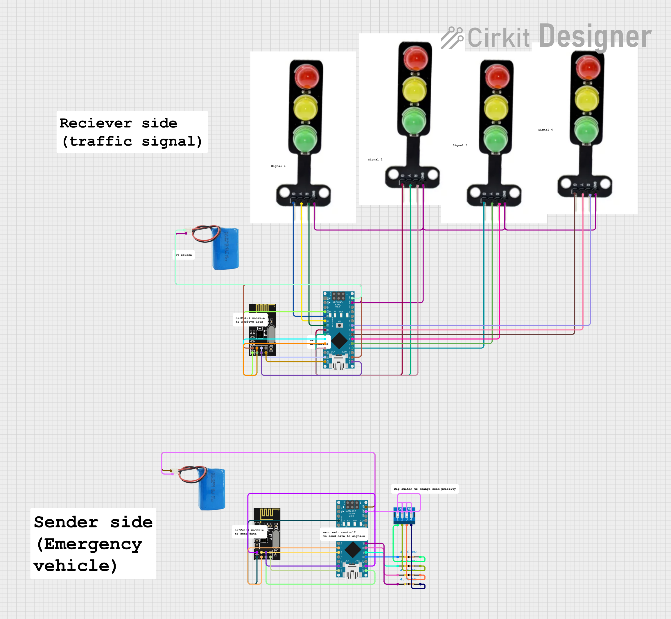
Smart Traffic Lights System for Prioritizing Emergency Vehicles
Summary
This document provides a detailed overview of a smart traffic lights system designed to prioritize emergency vehicles. The system uses multiple Arduino Nano microcontrollers, NRF24L01 wireless modules, traffic lights, and other components to detect emergency vehicles and change traffic lights accordingly. The system is powered by 5V batteries and includes resistors and a DIP switch for additional functionality.
Component List
Arduino Nano
- Description: A small, complete, and breadboard-friendly board based on the ATmega328P.
- Pins: D1/TX, D0/RX, RESET, GND, D2, D3, D4, D5, D6, D7, D8, D9, D10, D11/MOSI, D12/MISO, VIN, 5V, A7, A6, A5, A4, A3, A2, A1, A0, AREF, 3V3, D13/SCK
NRF24L01
- Description: A wireless transceiver module for short-range communication.
- Pins: IRQ (not used), MOSI, CSN, VCC (3V), GND, CE, SCK, MISO
DIP Switch 4 Position
- Description: A 4-position DIP switch for user input.
- Pins: 1, 2, 3, 4, 5, 6, 7, 8
Traffic Light
- Description: A traffic light module with green, yellow, and red LEDs.
- Pins: Green, yellow, red, GND
5V Battery
- Description: A 5V power source.
- Pins: positive, negative
Resistor
- Description: A resistor with a resistance of 4700 Ohms.
- Pins: pin1, pin2
Wiring Details
Arduino Nano
- GND connected to GND of NRF24L01
- D2 connected to Green of Traffic Light
- D3 connected to yellow of Traffic Light
- D4 connected to red of Traffic Light
- D5 connected to Green of Traffic Light
- D6 connected to yellow of Traffic Light
- D7 connected to CE of NRF24L01
- D8 connected to CSN of NRF24L01
- D9 connected to red of Traffic Light
- D11/MOSI connected to MOSI of NRF24L01
- D12/MISO connected to MISO of NRF24L01
- VIN connected to positive of 5V Battery
- GND connected to negative of 5V Battery, GND of Traffic Light
- A5 connected to red of Traffic Light
- A4 connected to yellow of Traffic Light
- A3 connected to Green of Traffic Light
- A2 connected to red of Traffic Light
- A1 connected to yellow of Traffic Light
- A0 connected to Green of Traffic Light
- 3V3 connected to VCC (3V) of NRF24L01
- D13/SCK connected to SCK of NRF24L01
NRF24L01
- GND connected to GND of Arduino Nano
- CE connected to D7 of Arduino Nano
- CSN connected to D8 of Arduino Nano
- MOSI connected to D11/MOSI of Arduino Nano
- MISO connected to D12/MISO of Arduino Nano
- VCC (3V) connected to 3V3 of Arduino Nano
- SCK connected to D13/SCK of Arduino Nano
Traffic Light
- Green connected to D2 of Arduino Nano
- yellow connected to D3 of Arduino Nano
- red connected to D4 of Arduino Nano
- GND connected to GND of Arduino Nano, negative of 5V Battery
5V Battery
- positive connected to VIN of Arduino Nano
- negative connected to GND of Arduino Nano, GND of Traffic Light
Resistor
- pin1 connected to A3 of Arduino Nano
- pin2 connected to 1 of DIP Switch 4 Position
DIP Switch 4 Position
- 1 connected to pin2 of Resistor
- 2 connected to pin2 of Resistor
- 3 connected to pin2 of Resistor
- 4 connected to pin2 of Resistor
- 5 connected to GND of Arduino Nano
- 6 connected to GND of Arduino Nano
- 7 connected to GND of Arduino Nano
- 8 connected to GND of Arduino Nano
Code Documentation
Arduino Nano (Instance 1)
/*
 * Smart Traffic Lights System for Prioritizing Emergency Vehicles
 * This code controls a set of traffic lights connected to an Arduino Nano.
 * The system prioritizes emergency vehicles by changing the traffic lights
 * to green when an emergency vehicle is detected.
 */

// Pin definitions for traffic lights
const int greenLight1 = 2;
const int yellowLight1 = 3;
const int redLight1 = 4;
const int greenLight2 = 5;
const int yellowLight2 = 6;
const int redLight2 = 9;
const int greenLight3 = A0;
const int yellowLight3 = A1;
const int redLight3 = A2;
const int greenLight4 = A3;
const int yellowLight4 = A4;
const int redLight4 = A5;

// NRF24L01 pin definitions
const int CE_PIN = 7;
const int CSN_PIN = 8;

void setup() {
  // Initialize traffic light pins as outputs
  pinMode(greenLight1, OUTPUT);
  pinMode(yellowLight1, OUTPUT);
  pinMode(redLight1, OUTPUT);
  pinMode(greenLight2, OUTPUT);
  pinMode(yellowLight2, OUTPUT);
  pinMode(redLight2, OUTPUT);
  pinMode(greenLight3, OUTPUT);
  pinMode(yellowLight3, OUTPUT);
  pinMode(redLight3, OUTPUT);
  pinMode(greenLight4, OUTPUT);
  pinMode(yellowLight4, OUTPUT);
  pinMode(redLight4, OUTPUT);

  // Initialize NRF24L01 pins
  pinMode(CE_PIN, OUTPUT);
  pinMode(CSN_PIN, OUTPUT);

  // Initialize serial communication
  Serial.begin(9600);

  // Initialize NRF24L01 (add your NRF24L01 initialization code here)
}

void loop() {
  // Check for emergency vehicle signal (add your signal detection code here)
  bool emergencyVehicleDetected = false; // Placeholder for actual detection logic

  if (emergencyVehicleDetected) {
    prioritizeEmergencyVehicle();
  } else {
    normalTrafficOperation();
  }
}

void prioritizeEmergencyVehicle() {
  // Turn all traffic lights to red except the one for emergency vehicle
  digitalWrite(redLight1, HIGH);
  digitalWrite(yellowLight1, LOW);
  digitalWrite(greenLight1, LOW);
  digitalWrite(redLight2, HIGH);
  digitalWrite(yellowLight2, LOW);
  digitalWrite(greenLight2, LOW);
  digitalWrite(redLight3, HIGH);
  digitalWrite(yellowLight3, LOW);
  digitalWrite(greenLight3, LOW);
  digitalWrite(redLight4, LOW);
  digitalWrite(yellowLight4, LOW);
  digitalWrite(greenLight4, HIGH);
}

void normalTrafficOperation() {
  // Normal traffic light sequence (add your traffic light sequence code here)
  // Example: Green -> Yellow -> Red for each traffic light
  digitalWrite(greenLight1, HIGH);
  delay(5000);
  digitalWrite(greenLight1, LOW);
  digitalWrite(yellowLight1, HIGH);
  delay(2000);
  digitalWrite(yellowLight1, LOW);
  digitalWrite(redLight1, HIGH);
  delay(5000);
  digitalWrite(redLight1, LOW);

  digitalWrite(greenLight2, HIGH);
  delay(5000);
  digitalWrite(greenLight2, LOW);
  digitalWrite(yellowLight2, HIGH);
  delay(2000);
  digitalWrite(yellowLight2, LOW);
  digitalWrite(redLight2, HIGH);
  delay(5000);
  digitalWrite(redLight2, LOW);

  digitalWrite(greenLight3, HIGH);
  delay(5000);
  digitalWrite(greenLight3, LOW);
  digitalWrite(yellowLight3, HIGH);
  delay(2000);
  digitalWrite(yellowLight3, LOW);
  digitalWrite(redLight3, HIGH);
  delay(5000);
  digitalWrite(redLight3, LOW);

  digitalWrite(greenLight4, HIGH);
  delay