
Arduino-Controlled Multi-Servo Positioning System with Potentiometer Feedback
View and Edit Project In Cirkit Designer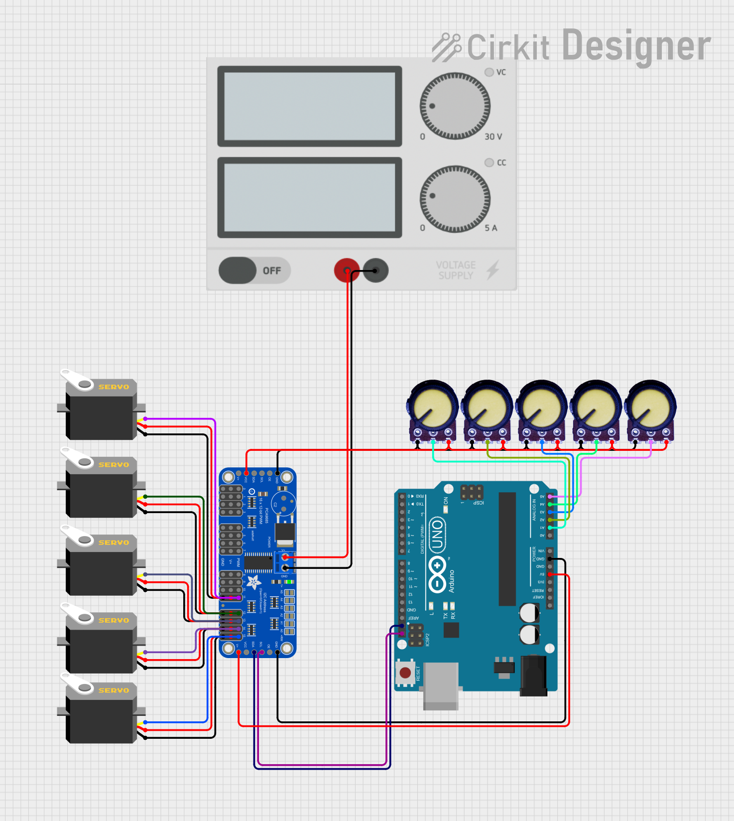
Circuit Documentation
Summary of the Circuit
This circuit is designed to control five servo motors using five potentiometers for position adjustment. An Arduino UNO microcontroller serves as the central processing unit, interfacing with an Adafruit 16-Channel 12-bit PWM Servo Driver via I2C communication to control the servos. The potentiometers provide analog input to the Arduino, which then translates these inputs into PWM signals to adjust the servos' positions. A separate power supply is included to provide adequate power to the servo driver and the servos.
Component List
Arduino UNO
- Microcontroller board based on the ATmega328P
- Features digital I/O pins, analog inputs, and various power outputs
Servo Motors (5x)
- Electrically controlled devices that can rotate to a specified position
- Each servo has three connections: ground (gnd), power (vcc), and control signal (pulse)
Adafruit 16-Channel 12-bit PWM Servo Driver - I2C
- An I2C-controlled PWM driver with a built-in clock
- Capable of driving multiple servos with precise timing
Potentiometers (5x)
- Variable resistors that provide a varying voltage output when turned
- Each potentiometer has three terminals: ground (GND), output (Output), and power (VCC)
Power Supply
- Provides power to the servo driver and servos
- Has positive (+) and negative (-) terminals
Wiring Details
Arduino UNO
5Vconnected to Adafruit PWM Servo Driver's5.0VGNDconnected to Adafruit PWM Servo Driver'sGNDA1toA5connected to the outputs of the five potentiometersSCLconnected to Adafruit PWM Servo Driver'sSCLSDAconnected to Adafruit PWM Servo Driver'sSDA
Servo Motors
- All servos'
gndconnected to Adafruit PWM Servo Driver'sGND - All servos'
vccconnected to Adafruit PWM Servo Driver's5.0V - Servos'
pulseconnected to Adafruit PWM Servo Driver'sPWM12,PWM11,PWM13,PWM14, andPWM15
Adafruit 16-Channel 12-bit PWM Servo Driver - I2C
5.0VandGNDconnected to Arduino UNO's5VandGNDSDAandSCLconnected to Arduino UNO'sSDAandSCLPWRINconnected to Power Supply's+GNDconnected to Power Supply's-VCCconnected to all potentiometers'VCCGNDconnected to all potentiometers'GNDPWM0toPWM15used to control servos
Potentiometers
- All potentiometers'
VCCconnected together and to Adafruit PWM Servo Driver'sVCC - All potentiometers'
GNDconnected together and to Adafruit PWM Servo Driver'sGND - Each potentiometer's
Outputconnected to a unique analog input on the Arduino UNO (A1toA5)
Power Supply
+connected to Adafruit PWM Servo Driver'sPWRIN-connected to Adafruit PWM Servo Driver'sGND
Documented Code
/*
 * This Arduino sketch controls 5 servos using 5 potentiometers.
 * Each potentiometer adjusts the position of a corresponding servo.
 * The Adafruit 16-Channel 12-bit PWM Servo Driver is used to control the servos.
 */

#include <Wire.h>
#include <Adafruit_PWMServoDriver.h>

Adafruit_PWMServoDriver pwm = Adafruit_PWMServoDriver();

// Servo and potentiometer mappings
const int potPins[5] = {A1, A2, A3, A4, A5};
const int servoChannels[5] = {12, 13, 14, 15, 11};

void setup() {
  Serial.begin(9600);
  pwm.begin();
  pwm.setPWMFreq(60);  // Analog servos run at ~60 Hz
}

void loop() {
  for (int i = 0; i < 5; i++) {
    int potValue = analogRead(potPins[i]);
    int servoPos = map(potValue, 0, 1023, 150, 600);
    pwm.setPWM(servoChannels[i], 0, servoPos);
  }
  delay(15);  // Small delay to prevent jitter
}
This code initializes the Adafruit PWM Servo Driver and sets up a loop to read the analog values from the potentiometers. It maps these values to a range suitable for servo control and sends the corresponding PWM signals to the servos through the driver.