
ESP32 CAM Wi-Fi Controlled Robotic System with Motor and Servo Control
View and Edit Project In Cirkit Designer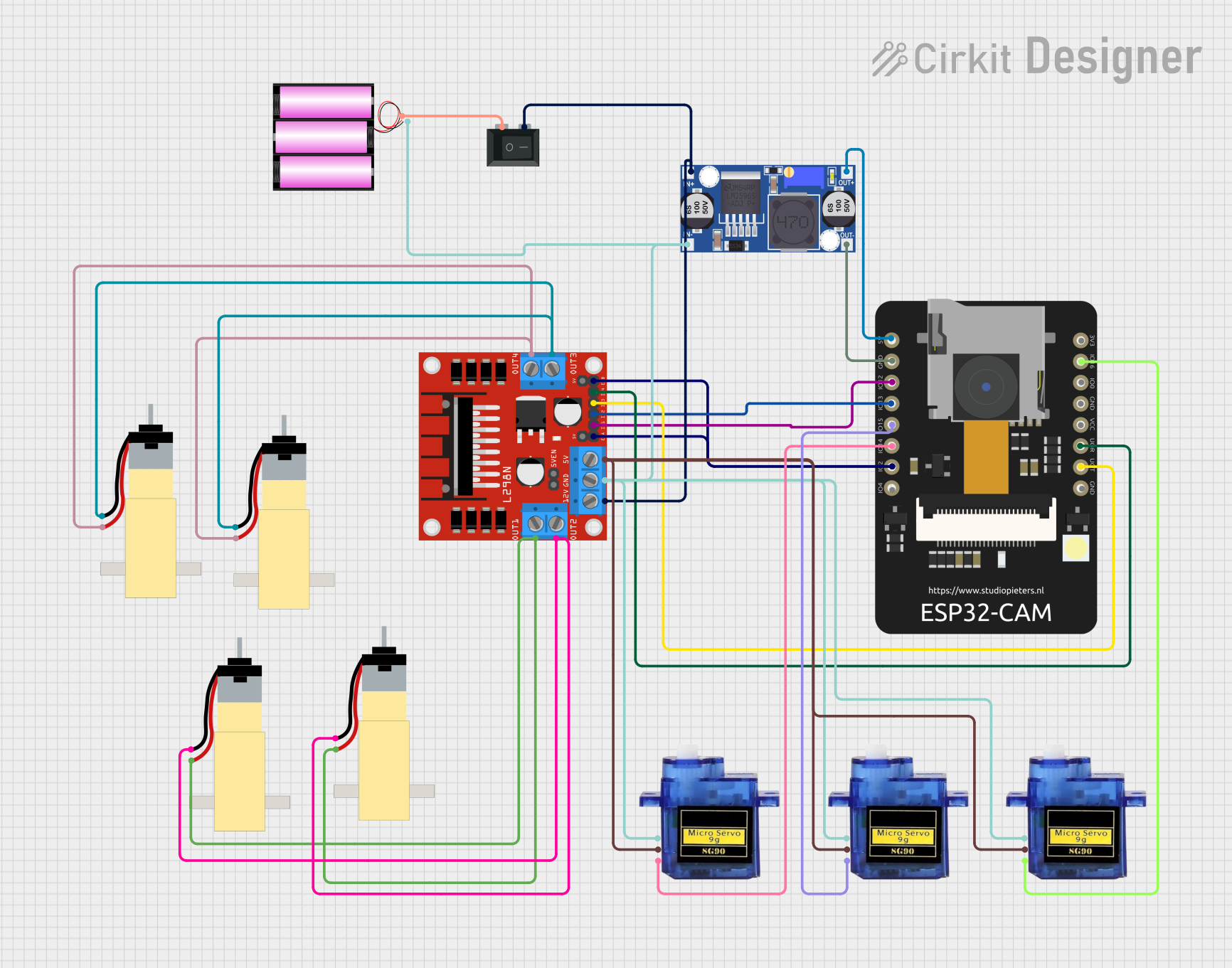
Circuit Documentation
Summary
This document provides a detailed overview of a circuit that includes an ESP32 CAM microcontroller, an L298N DC motor driver, a 12V battery, a rocker switch, a buck converter, multiple micro servos, and hobby gearmotors. The circuit is designed to control various motors and servos using the ESP32 CAM, with power regulation provided by a buck converter and a rocker switch for power control.
Component List
ESP32 CAM
- Description: A microcontroller with integrated Wi-Fi and Bluetooth, used for controlling the circuit.
- Pins: 5V, GND, GPIO12, GPIO13, GPIO15, GPIO14, GPIO2, GPIO4, 3.3V, GPIO16, GPIO0, 3.3V / 5V / P_OUT, GPIO3 / RX, GPIO1 / TX
L298N DC Motor Driver
- Description: A dual H-bridge motor driver that allows control of the speed and direction of two DC motors.
- Pins: OUT1, OUT2, 12V, GND, 5V, OUT3, OUT4, 5V-ENA-JMP-I, 5V-ENA-JMP-O, +5V-J1, +5V-J2, ENA, IN1, IN2, IN3, IN4, ENB
Battery 12V
- Description: A 12V battery used to power the circuit.
- Pins: +, -
Rocker Switch (SPST)
- Description: A single-pole single-throw switch used to control the power supply to the circuit.
- Pins: 1, 2
Buck Converter
- Description: A DC-DC converter used to step down the voltage from 12V to 5V.
- Pins: IN+, IN-, OUT+, OUT-
Micro Servo 9G
- Description: A small servo motor used for precise control of angular position.
- Pins: GND, +5V, PWM
Hobby Gearmotor with 48:1 Gearbox
- Description: A DC motor with a 48:1 gearbox for increased torque.
- Pins: pin 1, pin 2
Wiring Details
ESP32 CAM
- 5V connected to OUT+ of the Buck Converter
- GND connected to OUT- of the Buck Converter
- GPIO12 connected to IN1 of the L298N DC Motor Driver
- GPIO13 connected to IN2 of the L298N DC Motor Driver
- GPIO15 connected to PWM of the Micro Servo 9G
- GPIO14 connected to PWM of the Micro Servo 9G
- GPIO2 connected to ENA and ENB of the L298N DC Motor Driver
- GPIO16 connected to PWM of the Micro Servo 9G
- GPIO3 / RX connected to IN4 of the L298N DC Motor Driver
- GPIO1 / TX connected to IN3 of the L298N DC Motor Driver
L298N DC Motor Driver
- IN1 connected to GPIO12 of the ESP32 CAM
- IN2 connected to GPIO13 of the ESP32 CAM
- IN3 connected to GPIO1 / TX of the ESP32 CAM
- IN4 connected to GPIO3 / RX of the ESP32 CAM
- ENA and ENB connected to GPIO2 of the ESP32 CAM
- OUT1 connected to pin 2 of two Hobby Gearmotors
- OUT2 connected to pin 1 of two Hobby Gearmotors
- OUT3 connected to pin 1 of two Hobby Gearmotors
- OUT4 connected to pin 2 of two Hobby Gearmotors
- 12V connected to IN+ of the Buck Converter and pin 2 of the Rocker Switch
- GND connected to GND of three Micro Servos and - of the Battery
- 5V connected to +5V of three Micro Servos
Battery 12V
- + connected to pin 1 of the Rocker Switch
- - connected to GND of the L298N DC Motor Driver
Rocker Switch (SPST)
- 1 connected to + of the Battery
- 2 connected to 12V of the L298N DC Motor Driver and IN+ of the Buck Converter
Buck Converter
- IN+ connected to pin 2 of the Rocker Switch and 12V of the L298N DC Motor Driver
- IN- connected to GND of the L298N DC Motor Driver and - of the Battery
- OUT+ connected to 5V of the ESP32 CAM
- OUT- connected to GND of the ESP32 CAM
Micro Servo 9G
- GND of three Micro Servos connected to GND of the L298N DC Motor Driver
- +5V of three Micro Servos connected to 5V of the L298N DC Motor Driver
- PWM of one Micro Servo connected to GPIO15 of the ESP32 CAM
- PWM of another Micro Servo connected to GPIO14 of the ESP32 CAM
- PWM of another Micro Servo connected to GPIO16 of the ESP32 CAM
Hobby Gearmotor with 48:1 Gearbox
- pin 1 of two Hobby Gearmotors connected to OUT2 of the L298N DC Motor Driver
- pin 2 of two Hobby Gearmotors connected to OUT1 of the L298N DC Motor Driver
- pin 1 of two Hobby Gearmotors connected to OUT3 of the L298N DC Motor Driver
- pin 2 of two Hobby Gearmotors connected to OUT4 of the L298N DC Motor Driver
Code
No code is provided for this circuit.