
Wireless Joystick-Controlled Interface with Arduino Nano and NRF24L01
View and Edit Project In Cirkit Designer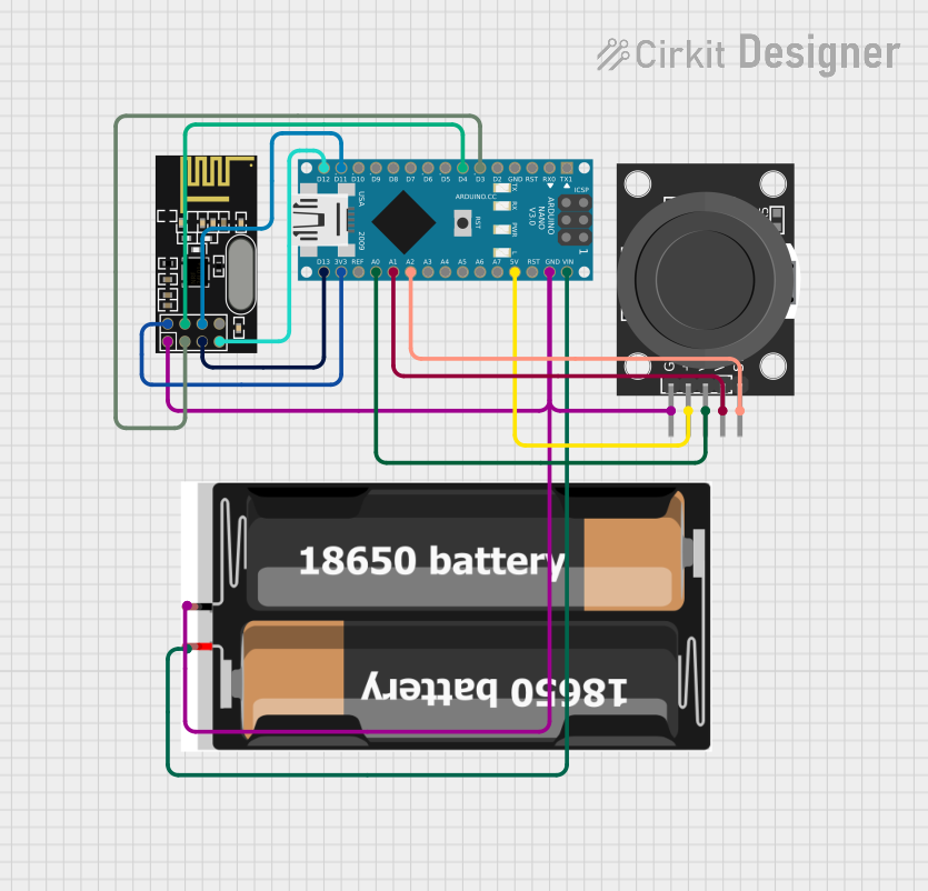
Circuit Documentation
Summary
This circuit integrates a KY-023 Dual Axis Joystick Module, an Arduino Nano microcontroller, an NRF24L01 wireless transceiver module, and a power source consisting of two 18650 batteries. The joystick module provides analog input to the Arduino Nano, which can process the input and communicate wirelessly via the NRF24L01 module. The 18650 batteries supply power to the circuit, with voltage regulation provided by the Arduino Nano for the NRF24L01 module.
Component List
KY-023 Dual Axis Joystick Module
- Description: A module that provides two analog outputs corresponding to the X and Y positions of the joystick, and a digital output that indicates the joystick button press.
- Pins: GND, +5V, VRx, VRy, SW
Arduino Nano
- Description: A compact microcontroller board based on the ATmega328P, with digital and analog I/O pins.
- Pins: D1/TX, D0/RX, RESET, GND, D2, D3, D4, D5, D6, D7, D8, D9, D10, D11/MOSI, D12/MISO, VIN, 5V, A7, A6, A5, A4, A3, A2, A1, A0, AREF, 3V3, D13/SCK
NRF24L01
- Description: A 2.4GHz wireless transceiver module, capable of sending and receiving data at various data rates.
- Pins: IRQ (not used), MOSI, CSN, VCC (3V), GND, CE, SCK, MISO
2x 18650 Batteries
- Description: A power source consisting of two lithium-ion batteries.
- Pins: vcc, gnd
Wiring Details
KY-023 Dual Axis Joystick Module
- GND connected to common ground
- +5V connected to Arduino Nano 5V
- VRx connected to Arduino Nano A0
- VRy connected to Arduino Nano A1
- SW connected to Arduino Nano A2
Arduino Nano
- GND connected to common ground
- 5V providing power to the KY-023 Dual Axis Joystick Module
- A0 receiving analog X-axis input from KY-023 Dual Axis Joystick Module
- A1 receiving analog Y-axis input from KY-023 Dual Axis Joystick Module
- A2 receiving button press signal from KY-023 Dual Axis Joystick Module
- D3 connected to NRF24L01 CE
- D4 connected to NRF24L01 CSN
- D11/MOSI connected to NRF24L01 MOSI
- D12/MISO connected to NRF24L01 MISO
- VIN connected to 18650 batteries vcc
- 3V3 providing power to NRF24L01 VCC (3V)
- D13/SCK connected to NRF24L01 SCK
NRF24L01
- GND connected to common ground
- MOSI connected to Arduino Nano D11/MOSI
- CSN connected to Arduino Nano D4
- VCC (3V) connected to Arduino Nano 3V3
- CE connected to Arduino Nano D3
- SCK connected to Arduino Nano D13/SCK
- MISO connected to Arduino Nano D12/MISO
2x 18650 Batteries
- vcc connected to Arduino Nano VIN
- gnd connected to common ground
Documented Code
Arduino Nano Code (sketch.ino)
void setup() {
  // put your setup code here, to run once:

}

void loop() {
  // put your main code here, to run repeatedly:

}
Note: The provided code is a template and does not include specific functionality. It should be populated with the setup and loop code required to read the joystick inputs, process them, and communicate via the NRF24L01 module.