
Arduino 101 Battery-Powered Fan and Motor Controller with USB Charging
View and Edit Project In Cirkit Designer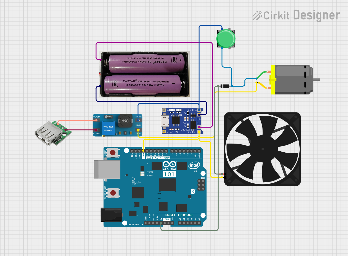
Circuit Documentation
Summary
This circuit is designed to manage power distribution and control a fan and a DC motor using an Arduino 101 microcontroller. The circuit includes a boost converter, a TP4056 battery charger, a diode, a pushbutton, a USB female connector, a 7.4V battery, a fan, and a DC motor. The Arduino 101 microcontroller is programmed to control the fan based on the state of the pushbutton.
Component List
Boost Converter MT3608
- Pins: OUTPUT +, OUTPUT -, INPUT +, INPUT -
- Description: Boost converter to step up voltage.
TP4056
- Pins: OUT-, B-, B+, OUT+, IN-, IN+
- Description: Lithium-ion battery charger module.
Fan
- Pins: GND, 5V
- Description: 5V DC fan.
DC Motor
- Pins: pin 1, pin 2
- Description: DC motor for mechanical movement.
Arduino 101
- Pins: A5/SCL, A4/SDA, AREF, GND, D13/SCK, D12/MISO, D11 PWM/MOSI, D10 PWM/SS, D9 PWM, D8, D7, D6 PWM, D5 PWM, D4, D3 PWM, D2, D1/TX, D0/RX, AIN, ioref, RESET, 3V3, 5V, VIN, A0, A1, A2, A3, ICSP MISO, ICSP SCK, ICSP MOSI
- Description: Microcontroller for controlling the circuit.
Diode
- Pins: cathode, anode
- Description: Diode for current direction control.
USB Female
- Pins: VCC, GND, -D, +D
- Description: USB female connector for power input.
7.4V Battery
- Pins: +, -
- Description: 7.4V rechargeable battery.
Pushbutton
- Pins: Pin 2, Pin 1, Pin 3, Pin 4
- Description: Pushbutton for user input.
Wiring Details
Boost Converter MT3608
- OUTPUT + connected to USB Female VCC
- OUTPUT - connected to USB Female GND
- INPUT + connected to TP4056 OUT+ and Pushbutton Pin 1
- INPUT - connected to TP4056 OUT-, Arduino 101 GND, Fan GND, and DC Motor pin 2
TP4056
- OUT+ connected to Boost Converter MT3608 INPUT + and Pushbutton Pin 1
- OUT- connected to Boost Converter MT3608 INPUT -, Arduino 101 GND, Fan GND, and DC Motor pin 2
- B- connected to 7.4V Battery -
- B+ connected to 7.4V Battery +
Fan
- GND connected to TP4056 OUT-, Arduino 101 GND, Boost Converter MT3608 INPUT -, and DC Motor pin 2
- 5V connected to Diode cathode and Arduino 101 5V
DC Motor
- pin 1 connected to Diode anode and Pushbutton Pin 2
- pin 2 connected to TP4056 OUT-, Arduino 101 GND, Boost Converter MT3608 INPUT -, and Fan GND
Arduino 101
- GND connected to TP4056 OUT-, Fan GND, Boost Converter MT3608 INPUT -, and DC Motor pin 2
- 5V connected to Diode cathode and Fan 5V
Diode
- cathode connected to Arduino 101 5V and Fan 5V
- anode connected to DC Motor pin 1 and Pushbutton Pin 2
USB Female
- VCC connected to Boost Converter MT3608 OUTPUT +
- GND connected to Boost Converter MT3608 OUTPUT -
7.4V Battery
- + connected to TP4056 B+
- - connected to TP4056 B-
Pushbutton
- Pin 1 connected to TP4056 OUT+ and Boost Converter MT3608 INPUT +
- Pin 2 connected to Diode anode and DC Motor pin 1
Code Documentation
const int buttonPin = 2;
const int fanPin = 5;

int buttonState = 0;

void setup() {
  pinMode(buttonPin, INPUT);
  pinMode(fanPin, OUTPUT);
  digitalWrite(fanPin, LOW);
}

void loop() {
  buttonState = digitalRead(buttonPin);

  if (buttonState == HIGH) {
    digitalWrite(fanPin, HIGH);
  } else {
    digitalWrite(fanPin, LOW);
  }
}
Code Explanation
- buttonPin: Pin 2 on the Arduino 101 is used to read the state of the pushbutton.
- fanPin: Pin 5 on the Arduino 101 is used to control the fan.
- buttonState: Variable to store the state of the pushbutton.
- setup(): Initializes the button pin as an input and the fan pin as an output. The fan is initially set to LOW (off).
- loop(): Continuously reads the state of the pushbutton. If the button is pressed (HIGH), the fan is turned on (HIGH). If the button is not pressed (LOW), the fan is turned off (LOW).