
Circuit Documentation
Summary of the Circuit
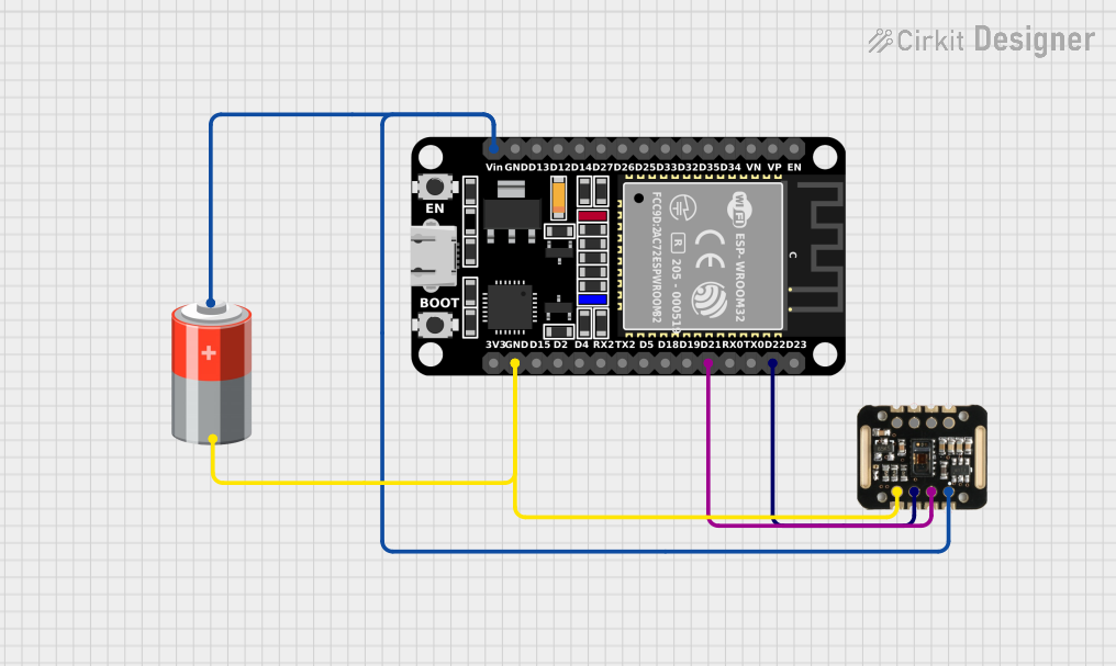
This circuit integrates a MAX30100 pulse oximeter and heart-rate sensor with an ESP32 microcontroller and is powered by a 5V battery. The ESP32 is responsible for interfacing with the MAX30100 sensor to collect and process the data. The sensor operates on a 5V supply, which is provided by the battery. The ESP32 communicates with the MAX30100 via I2C protocol, utilizing its SDA and SCL lines. The ground connections are shared across the components to complete the circuit.
Component List
MAX30100 Pulse Oximeter and Heart-Rate Sensor
- Pins: VIN, SDA, SCL, GND, RD, IRD, INT
- Description: The MAX30100 is an integrated pulse oximetry and heart-rate monitor sensor solution. It combines two LEDs, a photodetector, optimized optics, and low-noise analog signal processing to detect pulse oximetry and heart-rate signals.
ESP32 (30 pin) Microcontroller
- Pins: EN, VP, VN, D34, D35, D32, D33, D25, D26, D27, D14, D12, D13, GND, Vin, D23, D22, TX0, RX0, D21, D19, D18, D5, TX2, RX2, D4, D2, D15, 3V3
- Description: The ESP32 is a series of low-cost, low-power system on a chip microcontrollers with integrated Wi-Fi and dual-mode Bluetooth. It is equipped with a variety of peripherals, including capacitive touch, ADCs, DACs, UART, SPI, I2C, and much more.
5V Battery
- Pins: +, -
- Description: A power source providing a 5V supply to power the circuit components.
Wiring Details
MAX30100 Pulse Oximeter and Heart-Rate Sensor
- VIN: Connected to the 5V supply from the battery.
- SDA: Connected to the ESP32's D21 pin for I2C data communication.
- SCL: Connected to the ESP32's D22 pin for I2C clock signal.
- GND: Connected to the common ground in the circuit.
ESP32 (30 pin) Microcontroller
- Vin: Connected to the 5V supply from the battery.
- D21 (SDA): Connected to the SDA pin of the MAX30100 for I2C data communication.
- D22 (SCL): Connected to the SCL pin of the MAX30100 for I2C clock signal.
- GND: Connected to the common ground in the circuit.
5V Battery
- +: Connected to the VIN pin of the ESP32 and the VIN pin of the MAX30100 to supply power.
- -: Connected to the common ground in the circuit.
Documented Code
No code has been provided for the microcontroller. Typically, the code would initialize the I2C interface on the ESP32, configure the MAX30100 sensor, and implement a loop to read the sensor data and process it accordingly. Without the code, we cannot document further in this section.