Cirkit Designer
Your all-in-one circuit design IDE
Home /
Project Documentation
Bluetooth-Controlled LED Matrix Display with Arduino Nano

Circuit Documentation
Summary
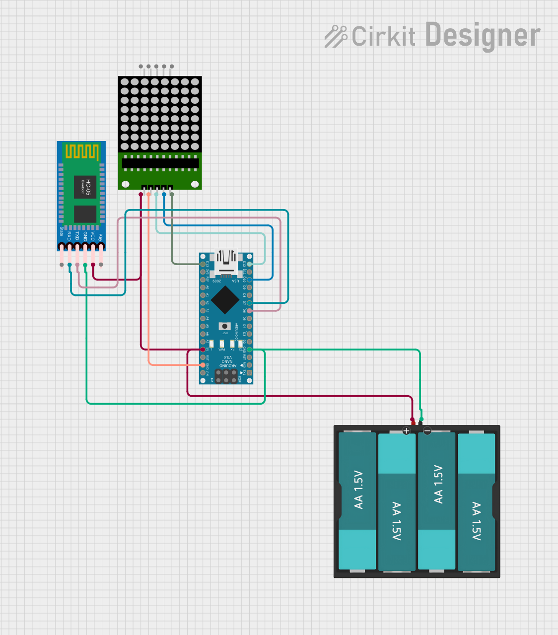
The circuit in question is designed to interface an HC-05 Bluetooth module with an Arduino Nano microcontroller to control an 8x8 LED matrix display. The Arduino Nano receives data via Bluetooth and drives the LED matrix to display characters or animations. The circuit is powered by a 6V battery pack consisting of four AA batteries.
Component List
HC-05 Bluetooth Module
- Description: A Bluetooth module for wireless data communication.
- Pins: Key, VCC, TXD, RXD, State, GND
8x8 LED Matrix
- Description: A matrix of LEDs arranged in an 8x8 grid, used for displaying characters or graphics.
- Pins: VCC, DIN, CLK, CS, GND
Arduino Nano
- Description: A small, complete, and breadboard-friendly microcontroller board based on the ATmega328P.
- Pins: D1/TX, D0/RX, RESET, GND, D2, D3, D4, D5, D6, D7, D8, D9, D10, D11/MOSI, D12/MISO, VIN, 5V, A7, A6, A5, A4, A3, A2, A1, A0, AREF, 3V3, D13/SCK
Battery AAx4 6V
- Description: A battery pack providing a 6V power supply to the circuit.
- Pins: VCC, GND
Wiring Details
HC-05 Bluetooth Module
- VCC connected to 6V power supply.
- TXD connected to Arduino Nano pin D6.
- RXD connected to Arduino Nano pin D7.
- GND connected to common ground.
8x8 LED Matrix
- VCC connected to 6V power supply.
- DIN connected to Arduino Nano pin D12/MISO.
- CLK connected to Arduino Nano pin D10.
- CS connected to Arduino Nano pin D13/SCK.
- GND connected to common ground.
Arduino Nano
- 5V connected to 6V power supply.
- GND connected to common ground.
- D6 connected to HC-05 Bluetooth Module TXD.
- D7 connected to HC-05 Bluetooth Module RXD.
- D10 connected to 8x8 LED Matrix CLK.
- D12/MISO connected to 8x8 LED Matrix DIN.
- D13/SCK connected to 8x8 LED Matrix CS.
Battery AAx4 6V
- VCC connected to HC-05 Bluetooth Module VCC, 8x8 LED Matrix VCC, and Arduino Nano 5V.
- GND connected to common ground.
Documented Code
#include <LEDMatrixDriver.hpp>
#include <SoftwareSerial.h>

SoftwareSerial mySerial(6, 7); // RX, TX-ble 7 rx

const uint8_t LEDMATRIX_CS_PIN = 10;

const int LEDMATRIX_SEGMENTS = 4;
const int LEDMATRIX_WIDTH    = LEDMATRIX_SEGMENTS * 10;

LEDMatrixDriver lmd(LEDMATRIX_SEGMENTS, LEDMATRIX_CS_PIN);

String str="hjhjbhj";
int str_len = str.length() + 1;

// Marquee speed (lower numbers = faster)
const int ANIM_DELAY = 70;

void setup() {
  Serial.begin(9600);
  mySerial.begin(9600);
  mySerial.println("test");
  // init the display
  lmd.setEnabled(true);
  lmd.setIntensity(9);   // 0 = low, 10 = high
}

int x=0, y=0;   // start top left

byte font[95][8] = {
  // Font data removed for brevity
};

void loop()
{
   if (mySerial.available()>0) {
     str=mySerial.readStringUntil('\n');
     Serial.println(str);
   }
   str_len = str.length() + 1;
   char char_array[str_len];
   str.toCharArray(char_array, str_len);

   // Draw the text to the current position
   int len = strlen(char_array);
   drawString(char_array, len, x, 0);
   // In case you wonder why we don't have to call lmd.clear() in every loop: The font has an opaque (black) background...

   // Toggle display of the new framebuffer
   lmd.display();

   // Wait to let the human read the display
   delay(ANIM_DELAY);

   // Advance to next coordinate
   if( --x < len * -8 ) {
     x = LEDMATRIX_WIDTH;
   }
}

/**
 * This function draws a string of the given length to the given position.
 */
void drawString(char* text, int len, int x, int y )
{
  for( int idx = 0; idx < len; idx ++ )
  {
    int c = text[idx] - 32;

    // stop if char is outside visible area
    if( x + idx * 8  > LEDMATRIX_WIDTH )
      return;

    // only draw if char is visible
    if( 8 + x + idx * 8 > 0 )
      drawSprite( font[c], x + idx * 8, y, 8, 8 );
  }
}

/**
 * This draws a sprite to the given position using the width and height supplied (usually 8x8)
 */
void drawSprite( byte* sprite, int x, int y, int width, int height )
{
  // The mask is used to get the column bit from the sprite row
  byte mask = B10000000;

  for( int iy = 0; iy < height; iy++ )
  {
    for( int ix = 0; ix < width; ix++ )
    {
      lmd.setPixel(x + ix, y + iy, (bool)(sprite[iy] & mask ));

      // shift the mask by one pixel to the right
      mask = mask >> 1;
    }

    // reset column mask
    mask = B10000000;
  }
}
Note: The font data array has been removed for brevity. The code is responsible for initializing the LED matrix and the Bluetooth module, receiving data from the Bluetooth module, and displaying the received text on the LED matrix. The drawString and drawSprite functions are used to render the text on the display.