
Arduino UNO R4 WiFi-Controlled Environmental Monitoring System with PH Sensor and Ultrasonic Distance Measurement
View and Edit Project In Cirkit Designer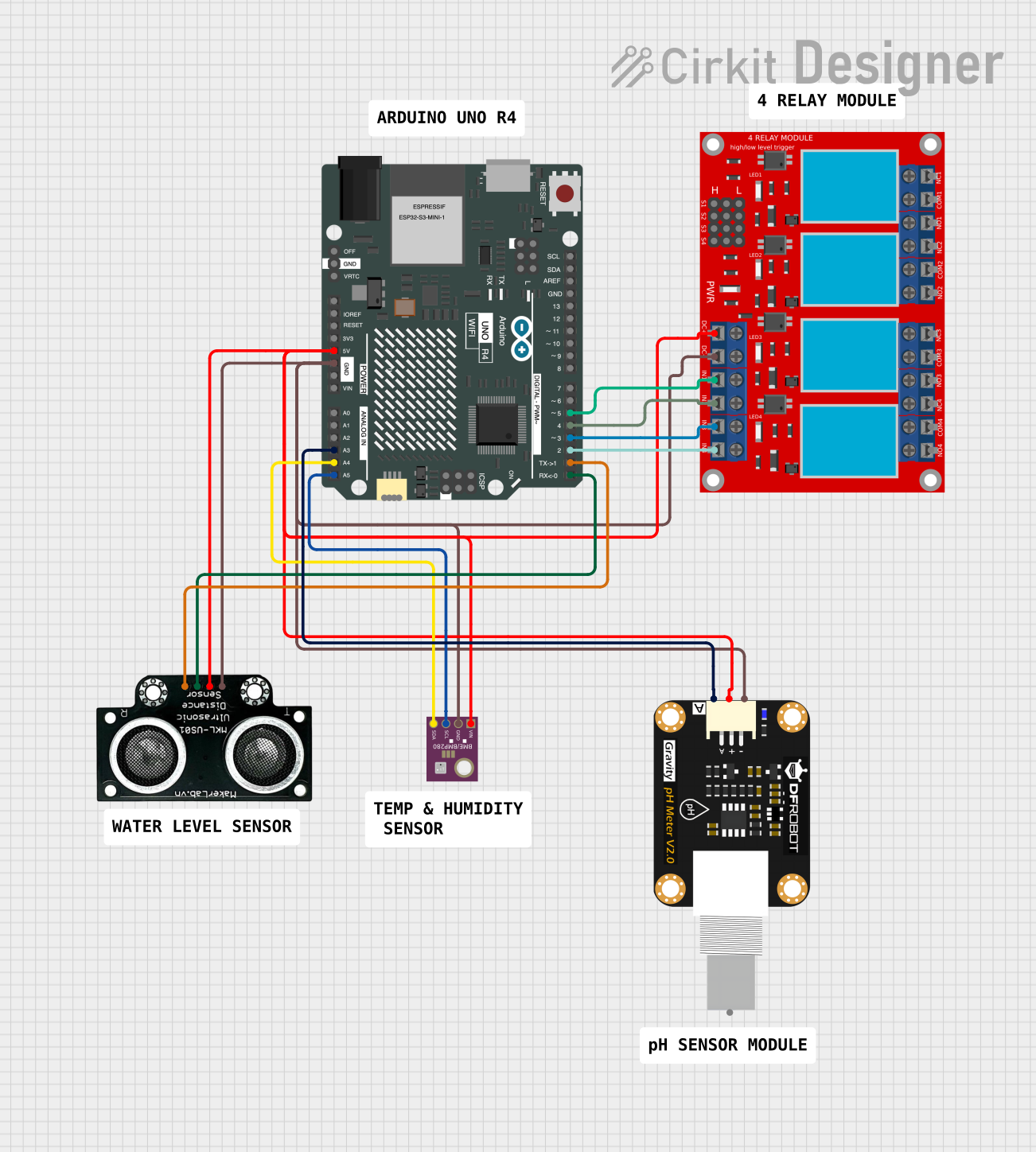
Circuit Documentation
Summary
This circuit integrates various sensors and a relay module with an Arduino UNO R4 WiFi microcontroller. The sensors include a BME/BMP280 for atmospheric measurements, a Modulo Sensor PH for pH level detection, and an MKE-S01 Ultrasonic Distance Sensor for measuring distances. A 4-channel relay module is used to control external loads. The Arduino UNO R4 WiFi serves as the central processing unit, interfacing with the sensors and controlling the relay module based on sensor inputs.
Component List
Arduino UNO R4 WiFi
- Microcontroller board with WiFi capability.
- Provides digital and analog I/O pins.
- Powers the sensors and relay module.
- Processes sensor data and controls the relay module.
Modulo Sensor PH
- Sensor for measuring the pH level of a solution.
- Outputs an analog signal corresponding to the pH level.
BME/BMP280
- Environmental sensor for measuring temperature, pressure, and humidity.
- Communicates with the Arduino via I2C protocol.
MKE-S01 Ultrasonic Distance Sensor
- Sensor for measuring distances using ultrasonic waves.
- Provides trigger and echo pins for interfacing with the Arduino.
4 Channel Relay Module
- Module with 4 relays to control up to four different loads.
- Each relay has normally open (N.O.), common (COM), and normally closed (N.C.) terminals.
- Controlled by digital signals from the Arduino.
Wiring Details
Arduino UNO R4 WiFi
5Vpin connected to the power supply pins of BME/BMP280, Modulo Sensor PH, MKE-S01 Ultrasonic Distance Sensor, and 4 channel relay module.GNDpin connected to the ground pins of BME/BMP280, Modulo Sensor PH, MKE-S01 Ultrasonic Distance Sensor, and 4 channel relay module.A3pin connected to the analog output of the Modulo Sensor PH.A4(SDA) pin connected to the SDA pin of BME/BMP280.A5(SCL) pin connected to the SCL pin of BME/BMP280.D0/RXpin connected to the TRIG pin of MKE-S01 Ultrasonic Distance Sensor.D1/TXpin connected to the ECHO pin of MKE-S01 Ultrasonic Distance Sensor.D2pin connected to the IN 4 pin of the 4 channel relay module.D3pin connected to the IN 3 pin of the 4 channel relay module.D4pin connected to the IN 2 pin of the 4 channel relay module.D5pin connected to the IN 1 pin of the 4 channel relay module.
Modulo Sensor PH
+pin connected to the 5V power supply.-pin connected to the ground.Apin connected to theA3pin of the Arduino UNO R4 WiFi.
BME/BMP280
VINpin connected to the 5V power supply.GNDpin connected to the ground.SDApin connected to theA4(SDA) pin of the Arduino UNO R4 WiFi.SCLpin connected to theA5(SCL) pin of the Arduino UNO R4 WiFi.
MKE-S01 Ultrasonic Distance Sensor
5Vpin connected to the 5V power supply.GNDpin connected to the ground.TRIGpin connected to theD0/RXpin of the Arduino UNO R4 WiFi.ECHOpin connected to theD1/TXpin of the Arduino UNO R4 WiFi.
4 Channel Relay Module
VCC+pin connected to the 5V power supply.VCC- (GND)pin connected to the ground.IN 1pin connected to theD5pin of the Arduino UNO R4 WiFi.IN 2pin connected to theD4pin of the Arduino UNO R4 WiFi.IN 3pin connected to theD3pin of the Arduino UNO R4 WiFi.IN 4pin connected to theD2pin of the Arduino UNO R4 WiFi.
Documented Code
Arduino UNO R4 WiFi Code (sketch.ino)
void setup() {
  // put your setup code here, to run once:

}

void loop() {
  // put your main code here, to run repeatedly:

}
Note: The provided code is a template and does not include specific functionality. It needs to be completed with the logic for sensor readings, data processing, and relay control based on the requirements of the circuit's application.