Cirkit Designer
Your all-in-one circuit design IDE
Home /
Project Documentation
Raspberry Pi 4b Controlled Dual-LED Indicator System
Circuit Documentation
Summary
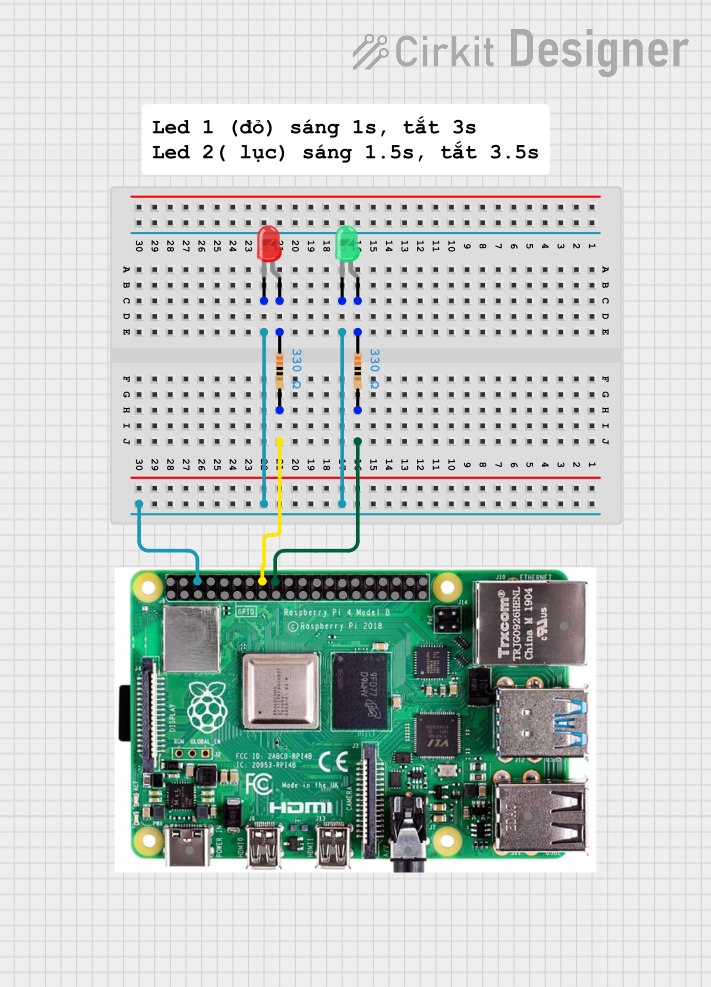
This circuit involves a Raspberry Pi 4b, two resistors, and two LEDs (one red and one green). The Raspberry Pi controls the LEDs through GPIO pins, with current-limiting resistors in series with each LED. The circuit is designed to demonstrate basic GPIO control using a Raspberry Pi.
Component List
Resistor (330 Ohms)
- Pins: pin1, pin2
- Description: Current-limiting resistor
- Purpose: Limits the current flowing through the LEDs to prevent damage
Raspberry Pi 4b
- Pins: 5V, 3V3, GPIO 2(SDA), GPIO 3(SCL), GPIO 4(GPCLK0), GND, GPIO 14(TXD), GPIO 15(RXD), GPIO 17, GPIO 27, GPIO 22, GPIO 10(MOSI), GPIO 9(MISO), GPIO 11(SCLK), GPIO 0(ID_SD), GPIO 5, GPIO 6, GPIO 13(PWM1), GPIO 19(PCM_FS), GPIO 26, GPIO 18(PCM_CLK), GPIO 23, GPIO 24, GPIO 25, GPIO 8(CE0), GPIO 7(CE1), GPIO 1(ID_SC), GPIO 12(PWM0), GPIO 16, GPIO 20(PCM_DIN), GPIO 21(PCM_DOUT), USB-C POWER PORT 5V/3A, MICRO HDMI PORT, 4 POLE STEREO AUDIO, 2X USB 2.0, 2X USB 3.0, GIGABIT ETHERNET
- Description: Single-board computer
- Purpose: Controls the LEDs through GPIO pins
LED: Two Pin (red)
- Pins: cathode, anode
- Description: Red LED
- Purpose: Visual indicator
LED: Two Pin (green)
- Pins: cathode, anode
- Description: Green LED
- Purpose: Visual indicator
Comment
- Description: Placeholder for comments
- Purpose: Not used in the circuit
Wiring Details
Resistor (330 Ohms)
Resistor 1
- pin1: Connected to the anode of the red LED
- pin2: Connected to GPIO 23 of the Raspberry Pi
Resistor 2
- pin1: Connected to the anode of the green LED
- pin2: Connected to GPIO 24 of the Raspberry Pi
Raspberry Pi 4b
GPIO 23
- Connected to pin2 of Resistor 1
GPIO 24
- Connected to pin2 of Resistor 2
GND
- Connected to the cathode of both the red and green LEDs
LED: Two Pin (red)
Anode
- Connected to pin1 of Resistor 1
Cathode
- Connected to GND of the Raspberry Pi
LED: Two Pin (green)
Anode
- Connected to pin1 of Resistor 2
Cathode
- Connected to GND of the Raspberry Pi
Documented Code
sketch.ino
// No code provided
documentation.txt
// No code provided
This documentation provides a comprehensive overview of the circuit, including a summary, detailed component list, wiring details, and documented code.