Cirkit Designer
Your all-in-one circuit design IDE
Home /
Project Documentation
Simple Pushbutton-Controlled LED Circuit
Circuit Documentation
Summary of the Circuit
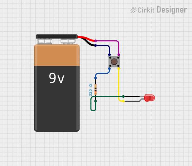
This circuit is a simple pushbutton-controlled LED lighting system powered by a 9V battery. When the pushbutton is pressed, the circuit is completed, allowing current to flow from the battery through a resistor and then through the LED, causing it to light up. The resistor is used to limit the current to a safe level for the LED.
Component List
9V Battery
- Description: A standard 9V battery used as the power source for the circuit.
Resistor
- Description: A passive two-terminal electrical component that implements electrical resistance as a circuit element.
- Resistance: 320 Ohms
Pushbutton
- Description: A simple switch mechanism for controlling some aspect of a machine or a process. It has four pins: two for the input side and two for the output side.
LED: Two Pin (red)
- Description: A red light-emitting diode (LED) that emits light when a current flows through it in the forward direction.
Wiring Details
9V Battery
- Negative Terminal:
- Connected to the input side of the Pushbutton (Pin 1).
- Positive Terminal:
- Connected to the output side of the Pushbutton (Pin 3).
Resistor
- Pin 1:
- Connected to the cathode of the LED.
- Pin 2:
- Connected to the input side of the Pushbutton (Pin 2).
Pushbutton
- Pin 1 (in):
- Connected to the negative terminal of the 9V Battery.
- Pin 2 (in):
- Connected to Pin 2 of the Resistor.
- Pin 3 (out):
- Connected to the positive terminal of the 9V Battery.
- Pin 4 (out):
- Connected to the anode of the LED.
LED: Two Pin (red)
- Cathode:
- Connected to Pin 1 of the Resistor.
- Anode:
- Connected to the output side of the Pushbutton (Pin 4).
Documented Code
There is no microcontroller or embedded code associated with this circuit. The functionality is purely hardware-based, relying on the physical actuation of the pushbutton to control the LED state.