
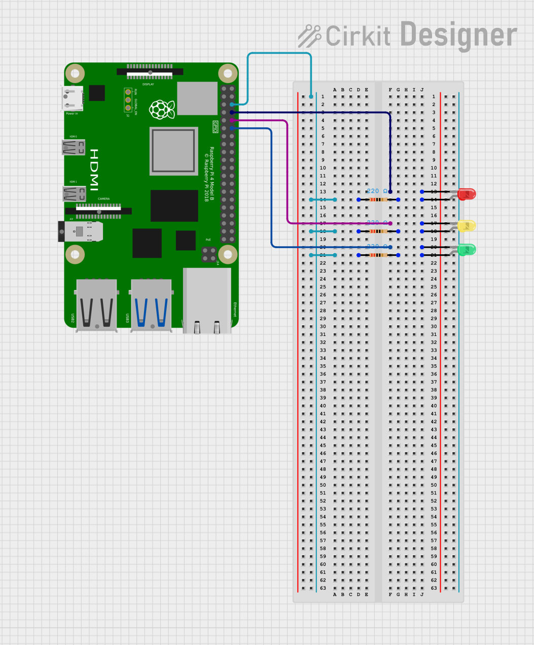
Circuit Documentation
Summary
This circuit consists of a Raspberry Pi 4B microcontroller unit (MCU) that controls three LEDs (red, yellow, and green). Each LED is connected to a GPIO pin on the Raspberry Pi 4B and is in series with a 220-ohm resistor to limit the current. The cathodes of the LEDs are connected directly to the GPIO pins, while the anodes are connected to the resistors, which in turn are connected to the ground (GND) pin of the Raspberry Pi 4B.
Component List
LEDs
- LED (Red): A two-pin red LED.
- LED (Yellow): A two-pin yellow LED.
- LED (Green): A two-pin green LED.
Microcontroller
- Raspberry Pi 4B: A microcontroller with multiple GPIO pins, power pins, and other interfaces.
Resistors
- Resistor (220 Ohms): Three resistors each with a resistance of 220 Ohms to limit the current through the LEDs.
Wiring Details
LED (Red)
- Cathode: Connected to GPIO14 of the Raspberry Pi 4B.
- Anode: Connected to a 220-ohm resistor.
LED (Yellow)
- Cathode: Connected to GPIO15 of the Raspberry Pi 4B.
- Anode: Connected to a 220-ohm resistor.
LED (Green)
- Cathode: Connected to GPIO18 of the Raspberry Pi 4B.
- Anode: Connected to a 220-ohm resistor.
Resistor (220 Ohms)
- One end: Connected to the anode of the corresponding LED.
- Other end: Connected to the GND pin of the Raspberry Pi 4B.
Raspberry Pi 4B
- GPIO14: Connected to the cathode of the red LED.
- GPIO15: Connected to the cathode of the yellow LED.
- GPIO18: Connected to the cathode of the green LED.
- GND: Connected to one end of each 220-ohm resistor.
Documented Code
The following code is intended to be run on the Raspberry Pi 4B microcontroller. The code is written in the Arduino programming language (.ino file extension) and is structured with a setup() function that runs once at the start and a loop() function that runs repeatedly.
void setup() {
  // put your setup code here, to run once:

}

void loop() {
  // put your main code here, to run repeatedly:

}
The code provided is a template and does not contain any specific logic to control the LEDs. To control the LEDs, the GPIO pins would need to be set as outputs in the setup() function, and then turned on and off in the loop() function using digital write commands.