
ESP32-Based Smart Environment Monitoring System with GPS Tracking and OLED Display
View and Edit Project In Cirkit Designer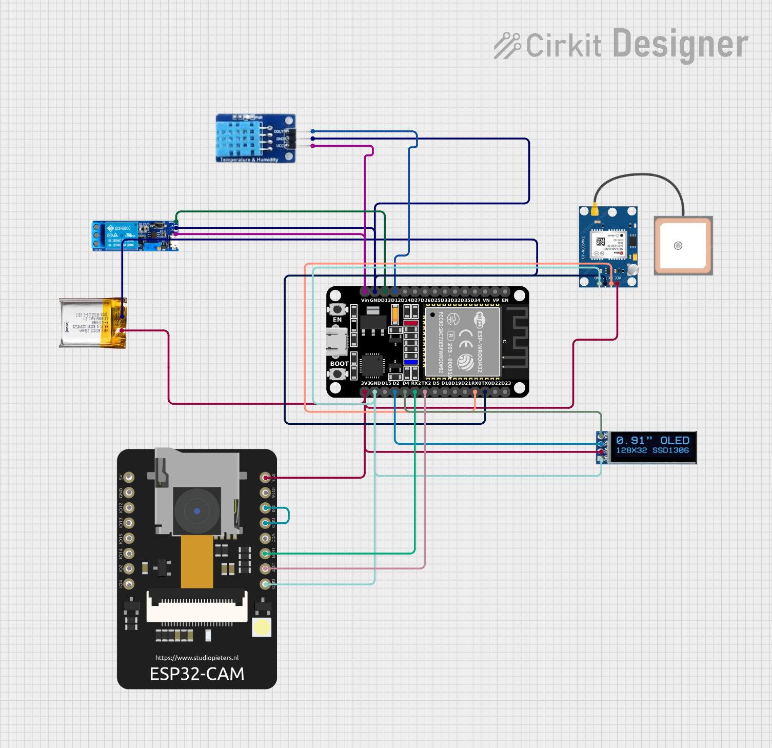
Circuit Documentation
Summary
This circuit is designed to control the temperature of a system, monitor driver behavior using a camera module, control a relay module to avoid high currents, display results on an OLED display, and find the location of the vehicle using a GPS module. The central processing unit of the circuit is an ESP32 microcontroller, which interfaces with a DHT11 temperature and humidity sensor, a relay module, an OLED display, a GPS module, and an ESP32 CAM module. The ESP32 also manages power distribution to the components and communicates with the GPS module via serial communication.
Component List
ESP32 (30 pin)
- Description: A microcontroller with Wi-Fi and Bluetooth capabilities, featuring a wide range of GPIO pins.
- Pins: EN, VP, VN, D34, D35, D32, D33, D25, D26, D27, D14, D12, D13, GND, Vin, D23, D22, TX0, RX0, D21, D19, D18, D5, TX2, RX2, D4, D2, D15, 3V3
DHT11
- Description: A basic, ultra-low-cost digital temperature and humidity sensor.
- Pins: DATA, GND, VCC
ESP32 CAM
- Description: A small-sized ESP32-based camera module.
- Pins: 5V, GND, GPIO12, GPIO13, GPIO15, GPIO14, GPIO2, GPIO4, 3.3V, GPIO16, GPIO0, 3.3V / 5V / P_OUT, GPIO3 / RX, GPIO1 / TX
Relay module 5v-30v
- Description: An electrically operated switch that allows you to turn on or off a higher power circuit using a lower power signal.
- Pins: common contact, normally open, normally closed, trigger, V-, V+
GPS NEO 6M
- Description: A compact GPS module for location-based applications.
- Pins: VCC, RX, TX, GND
3.7v LiPo
- Description: A rechargeable lithium polymer battery used for powering the circuit.
- Pins: +Ve, GND
OLED Display 128x32
- Description: A small display for showing text and graphics.
- Pins: SDA, SCL, VCC, GND
Wiring Details
ESP32 (30 pin)
- D12 connected to DHT11 DATA
- D13 connected to Relay module trigger
- GND connected to GND of DHT11, Relay module, ESP32 CAM, GPS NEO 6M, OLED Display
- Vin connected to Relay module V+
- TX0 connected to GPS NEO 6M TX
- RX0 connected to GPS NEO 6M RX
- TX2 connected to ESP32 CAM TX
- RX2 connected to ESP32 CAM RX
- D4 connected to OLED Display SDA
- D2 connected to OLED Display SCL
- 3V3 connected to VCC of ESP32 CAM, GPS NEO 6M, OLED Display
DHT11
- DATA connected to ESP32 D12
- GND connected to common GND
- VCC connected to ESP32 Vin
ESP32 CAM
- GND connected to common GND
- 3.3V connected to ESP32 3V3
- GPIO1 / TX connected to ESP32 TX2
- GPIO3 / RX connected to ESP32 RX2
- GPIO0 connected to GND (for programming mode)
Relay module 5v-30v
- trigger connected to ESP32 D13
- V- connected to common GND
- V+ connected to ESP32 Vin
GPS NEO 6M
- TX connected to ESP32 TX0
- RX connected to ESP32 RX0
- GND connected to common GND
- VCC connected to ESP32 3V3
3.7v LiPo
- +Ve connected to ESP32 CAM 3.3V, GPS NEO 6M VCC, OLED Display VCC
- GND connected to common GND
OLED Display 128x32
- SDA connected to ESP32 D4
- SCL connected to ESP32 D2
- VCC connected to ESP32 3V3
- GND connected to common GND
Documented Code
/*
 * This Arduino Sketch is designed to control the temperature of a system, monitor
 * driver behavior using a camera module, control a relay module to avoid high
 * currents, display results on an OLED display, and find the location of the
 * vehicle using a GPS module.
 */
#include <DHT.h>
#include <Wire.h>
#include <Adafruit_GFX.h>
#include <Adafruit_SSD1306.h>

#define DHTPIN 12          // Define the pin connected to the DHT11 data pin
#define DHTTYPE DHT11      // Define the type of DHT sensor
#define RELAY_PIN 13       // Define the pin connected to the Relay module trigger
#define OLED_RESET -1      // Define the reset pin for the OLED display (not used)
#define SCREEN_WIDTH 128   // Define the width of the OLED display
#define SCREEN_HEIGHT 32   // Define the height of the OLED display
#define OLED_I2C_ADDRESS 0x3C // Define the I2C address for the OLED display

DHT dht(DHTPIN, DHTTYPE); // Initialize the DHT sensor
Adafruit_SSD1306 display(SCREEN_WIDTH, SCREEN_HEIGHT, &Wire, OLED_RESET); // Initialize the OLED display

void setup() {
  Serial.begin(115200); // Start the serial communication
  Serial1.begin(9600);  // Use Serial1 for GPS communication
  dht.begin();          // Start the DHT sensor
  pinMode(RELAY_PIN, OUTPUT); // Set the relay pin as an output
  digitalWrite(RELAY_PIN, LOW); // Ensure the relay is off
  // Initialize the OLED display
  if(!display.begin(SSD1306_I2C_ADDRESS, OLED_I2C_ADDRESS)) {
    Serial.println(F("SSD1306 allocation failed"));
    for(;;); // Infinite loop if the display cannot be initialized
  }
  display.display(); // Show the initial display buffer
  delay(2000);       // Wait for 2 seconds
  display.clearDisplay(); // Clear the display buffer
}

void loop() {
  float temp = dht.readTemperature(); // Read the temperature from the DHT sensor
  if (isnan(temp)) { // Check if the reading failed
    Serial.println(F("Failed to read from DHT sensor!"));
    return; // Skip the rest of the loop if the reading failed
  }
  // Control the relay based on the temperature
  if (temp > 15) {
    digitalWrite(RELAY_PIN, HIGH); // Turn on the relay if the temperature is above 15 degrees Celsius
  } else {
    digitalWrite(RELAY_PIN, LOW);  // Turn off the relay otherwise
  }
  // Display the temperature on the OLED display
  display.clearDisplay();
  display.setTextSize(1);
  display.setTextColor(SSD1306_WHITE);
  display.setCursor(0, 0);
  display.print(F("Temp: "));
  display.print(temp);
  display.print(F(" C"));
  display.display();
  // Read data from the GPS module and output it to the serial monitor
  while (Serial1.available() > 0) {
    char c = Serial1.read();
    Serial.write(c);
  }
  delay(2000); // Wait for 2 seconds before repeating the loop
}
This code is responsible for initializing the components connected to the ESP32, reading temperature data from the DHT11 sensor, controlling the relay module based on the temperature, displaying the temperature on the OLED display, and reading data from the GPS module. The ESP32 uses two serial interfaces: the default Serial for debugging and Serial1 for GPS communication.