
Circuit Documentation
Summary
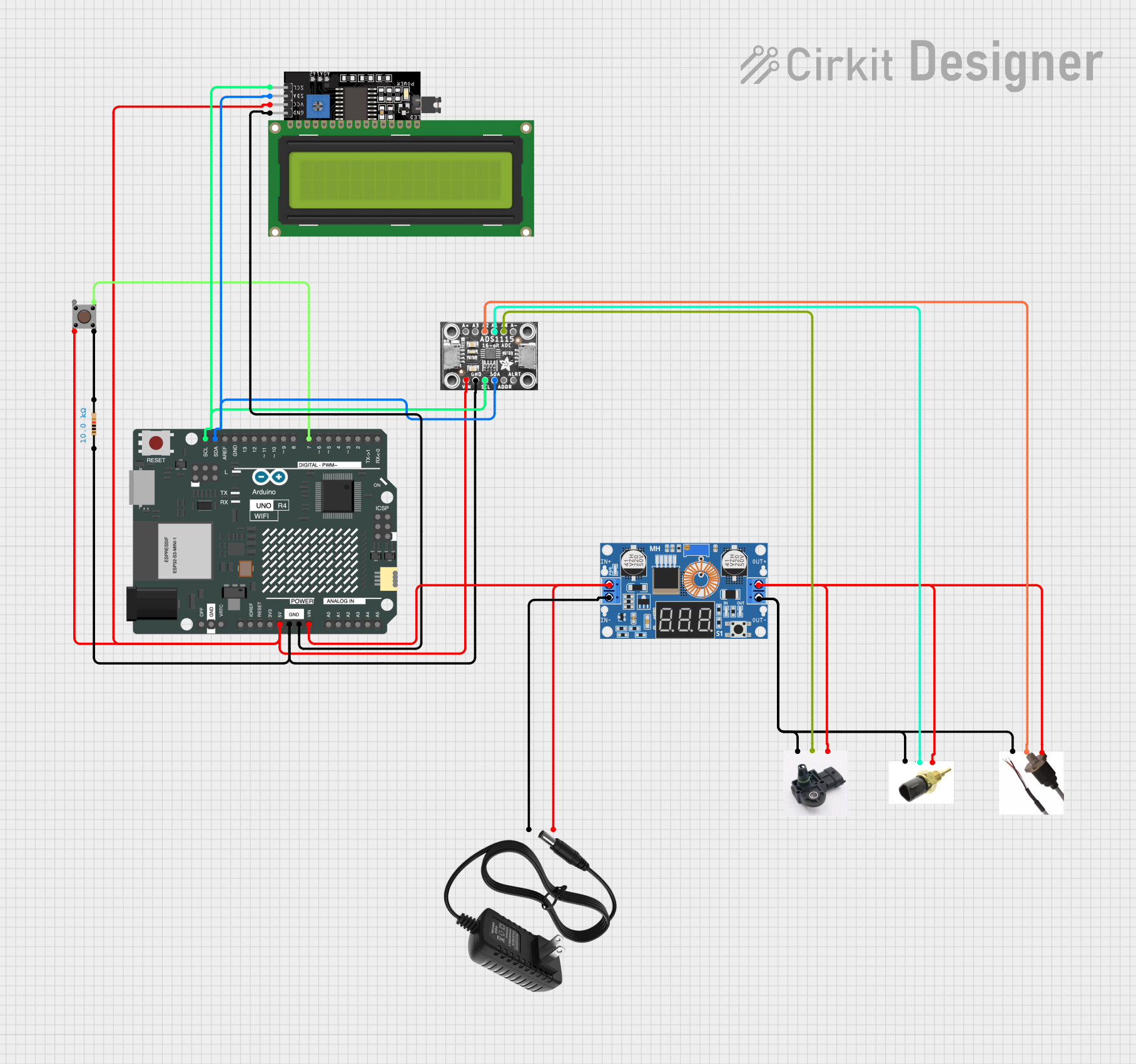
This document provides a detailed overview of a circuit that includes a variety of components such as sensors, a microcontroller, a display, and power management modules. The circuit is designed to interface with an Arduino UNO R4 WiFi microcontroller, which serves as the central processing unit. The components are interconnected to perform analog-to-digital conversions, display information, and respond to user input through a pushbutton. The circuit is powered by a 12V power supply, which is stepped down to the required voltages for the different components.
Component List
ADS1115 16-Bit ADC - 4 Channel
- Description: A precision, low-power, 16-bit analog-to-digital converter with 4 channels.
- Pins: A3, VIN, GND, SCL, SDA, ADDR, A+, A2, A1, A0, A-, ALRT
Honeywell MLH100PGL06A
- Description: A pressure sensor (specific details not provided).
- Pins: Not specified
Honda 37870-MBG-003
- Description: A temperature sensor (specific details not provided).
- Pins: Not specified
Bosch 261230217
- Description: A sensor (specific details not provided).
- Pins: Not specified
XL4015 5A DC Buck Step-down
- Description: A DC-DC step-down (buck) converter capable of driving a 5A load.
- Pins: Output +, Output -, Input +, Input -
Arduino UNO R4 WiFi
- Description: A microcontroller board based on the ATmega328 with integrated WiFi.
- Pins: OFF, GND, VRTC, IIC0_SCL, IIC0_SDA, 3V3, GPIO 41, GPIO 0, GPIO 42, GPIO 43, GPIO 44, BOOT, IOREF, RESET, 5V, VIN, A0, A1, A2, A3, A4, A5, RSPCKA, CIPO, COPI, D0/RX, D1/TX, D2, D3, D4, D5, D6, D7, D8, D9, D10, D11, D12, D13, AREF, SDA, SCL
Pushbutton
- Description: A simple pushbutton switch.
- Pins: Pin 3 (out), Pin 4 (out), Pin 1 (in), Pin 2 (in)
Resistor
- Description: A passive two-terminal electrical component that implements electrical resistance as a circuit element.
- Pins: pin1, pin2
- Properties: Resistance: 10000 Ohms
LCD Display 16x4 I2C
- Description: A 16x4 character LCD display with an I2C interface.
- Pins: SCL, SDA, VCC, GND
12v Power Supply
- Description: A power supply that provides a 12V output.
- Pins: +, -
Wiring Details
ADS1115 16-Bit ADC - 4 Channel
- VIN connected to 5V power net
- GND connected to ground net
- SCL connected to I2C clock net
- SDA connected to I2C data net
- A2 connected to Honeywell MLH100PGL06A
- A1 connected to Honda 37870-MBG-003
- A0 connected to Bosch 261230217
Honeywell MLH100PGL06A
- Connected to ADS1115 A2
Honda 37870-MBG-003
- Connected to ADS1115 A1
- Connected to common sensor net with Bosch 261230217 and Honeywell MLH100PGL06A
Bosch 261230217
- Connected to ADS1115 A0
- Connected to common sensor net with Honda 37870-MBG-003 and Honeywell MLH100PGL06A
XL4015 5A DC Buck Step-down
- Output + connected to common sensor net
- Output - connected to ground net
- Input + connected to 12V power supply +
- Input - connected to 12V power supply -
Arduino UNO R4 WiFi
- 5V connected to 5V power net
- GND connected to ground net
- SCL connected to I2C clock net
- SDA connected to I2C data net
- VIN connected to 12V power supply +
- D7 connected to Pushbutton Pin 3 (out)
Pushbutton
- Pin 2 (in) connected to 5V power net
- Pin 3 (out) connected to Arduino UNO R4 WiFi D7
- Pin 4 (out) connected to Resistor pin2
Resistor
- pin1 connected to ground net
- pin2 connected to Pushbutton Pin 4 (out)
LCD Display 16x4 I2C
- SCL connected to I2C clock net
- SDA connected to I2C data net
- VCC connected to 5V power net
- GND connected to ground net
12v Power Supply
-
- connected to XL4015 Input +
-
- connected to XL4015 Input -
Documented Code
Arduino UNO R4 WiFi Code (sketch.ino)
void setup() {
  // put your setup code here, to run once:

}

void loop() {
  // put your main code here, to run repeatedly:

}
Note: The provided code is a template and does not include any functionality. It needs to be populated with the logic to interact with the connected components.