
Arduino-Controlled Solar-Powered Robot with Bluetooth and Ultrasonic Sensing
View and Edit Project In Cirkit Designer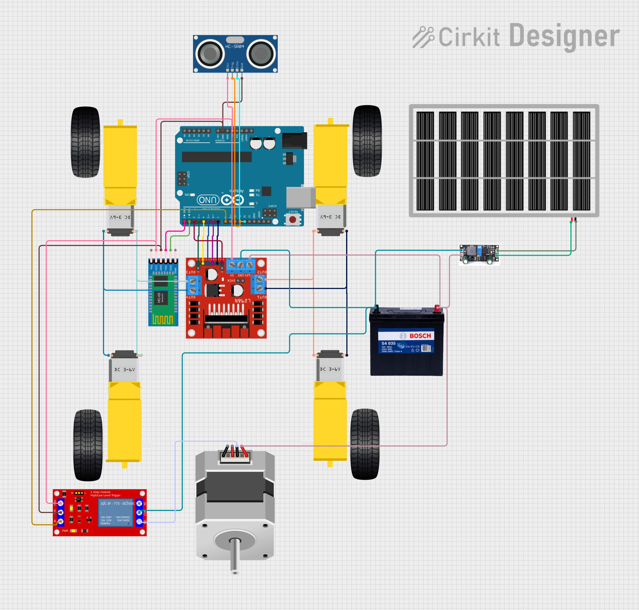
Circuit Documentation
Summary
The circuit in question appears to be designed for a mobile robotic platform, featuring motor control, power management, and communication capabilities. It includes gearmotors for movement, a motor driver for controlling the gearmotors, an Arduino UNO microcontroller for logic operations, a solar panel and charge controller for energy harvesting, a battery for power storage, a Bluetooth module for wireless communication, an ultrasonic sensor for distance measurement, a relay module for switching high-power circuits, and a stepper motor for precision movement.
Component List
Gearmotor DC Wheels (Left and Right)
- Description: These are DC gearmotors used for the left and right wheels of the robot, providing the necessary torque for movement.
- Pins: PIN1, PIN2
L298N DC Motor Driver
- Description: A motor driver module capable of driving up to four DC motors or two stepper motors. It is used to control the direction and speed of the motors.
- Pins: OUT1, OUT2, 12V, GND, 5V, OUT3, OUT4, 5V-ENA-JMP-I, 5V-ENA-JMP-O, +5V-J1, +5V-J2, ENA, IN1, IN2, IN3, IN4, ENB
Arduino UNO
- Description: A microcontroller board based on the ATmega328P. It is used to implement the control logic for the robot's operations.
- Pins: UNUSED, IOREF, Reset, 3.3V, 5V, GND, Vin, A0-A5, SCL, SDA, AREF, D0-D13
Solar Panel
- Description: A photovoltaic panel that converts sunlight into electrical energy, used to charge the battery.
- Pins: GND, VCC
Charge Controller
- Description: Manages the charging of the battery from the solar panel to prevent overcharging and deep discharge.
- Pins: GND, BAT, Vin
12V 200Ah Battery
- Description: A rechargeable battery that stores electrical energy for powering the robot.
- Pins: GND, 12V
HC-05 Bluetooth Module
- Description: A wireless communication module that enables Bluetooth connectivity for remote control or data transmission.
- Pins: Key, VCC, TXD, RXD, State, GND
Stepper Motor (Bipolar)
- Description: A bipolar stepper motor used for precise control of movement, likely for a specific part of the robot.
- Pins: D, B, C, A
HC-SR04 Ultrasonic Sensor
- Description: An ultrasonic distance sensor that measures the distance to an object by emitting ultrasonic waves.
- Pins: VCC, TRIG, ECHO, GND
1 Channel 5V Relay Module
- Description: An electromechanical switch that allows the Arduino to control high power devices.
- Pins: VCC+, VCC- (GND), IN, N.O., COM, N.C.
Wiring Details
Gearmotor DC Wheels (Left and Right)
- Connected to the L298N motor driver's OUT1, OUT2, OUT3, and OUT4 for motor control signals.
L298N DC Motor Driver
- 12V and GND pins are connected to the battery for power.
- OUT1, OUT2, OUT3, and OUT4 are connected to the gearmotors.
- ENA, ENB, IN1, IN2, IN3, and IN4 are connected to the Arduino UNO for motor control.
- 5V pin provides power to the HC-SR04 Ultrasonic Sensor, 1 Channel 5V Relay Module, and HC-05 Bluetooth Module.
Arduino UNO
- Digital pins D2, D3, D4, D5, D6, D7, D8, D11, and D12 are used for controlling the L298N motor driver, HC-SR04 Ultrasonic Sensor, and 1 Channel 5V Relay Module.
- Pins D0 and D1 are used for RX and TX communication with the HC-05 Bluetooth Module.
- 5V and GND pins provide power and ground connections to the L298N motor driver, HC-SR04 Ultrasonic Sensor, 1 Channel 5V Relay Module, and HC-05 Bluetooth Module.
Solar Panel
- VCC and GND pins are connected to the charge controller for charging the battery.
Charge Controller
- BAT pin is connected to the battery.
- Vin and GND pins are connected to the solar panel.
12V 200Ah Battery
- 12V and GND pins provide power to the L298N motor driver.
HC-05 Bluetooth Module
- VCC and GND pins are powered by the L298N motor driver.
- TXD and RXD pins are connected to the Arduino UNO for serial communication.
Stepper Motor (Bipolar)
- Connected to the L298N motor driver for control signals and to the 1 Channel 5V Relay Module for switching.
HC-SR04 Ultrasonic Sensor
- VCC and GND pins are powered by the L298N motor driver.
- TRIG and ECHO pins are connected to the Arduino UNO for triggering and receiving distance measurements.
1 Channel 5V Relay Module
- VCC+ and VCC- (GND) pins are powered by the L298N motor driver.
- IN pin is controlled by the Arduino UNO.
- N.O. and COM pins are connected to the Stepper Motor (Bipolar) for switching.
Documented Code
void setup() {
  // put your setup code here, to run once:

}

void loop() {
  // put your main code here, to run repeatedly:

}
The provided code is a template for an Arduino sketch with empty setup and loop functions. The setup function is intended to initialize settings or pin modes, and the loop function will contain the main logic that the Arduino will execute repeatedly. Additional code is required to implement the control logic for the components connected to the Arduino.