
Circuit Documentation
Summary
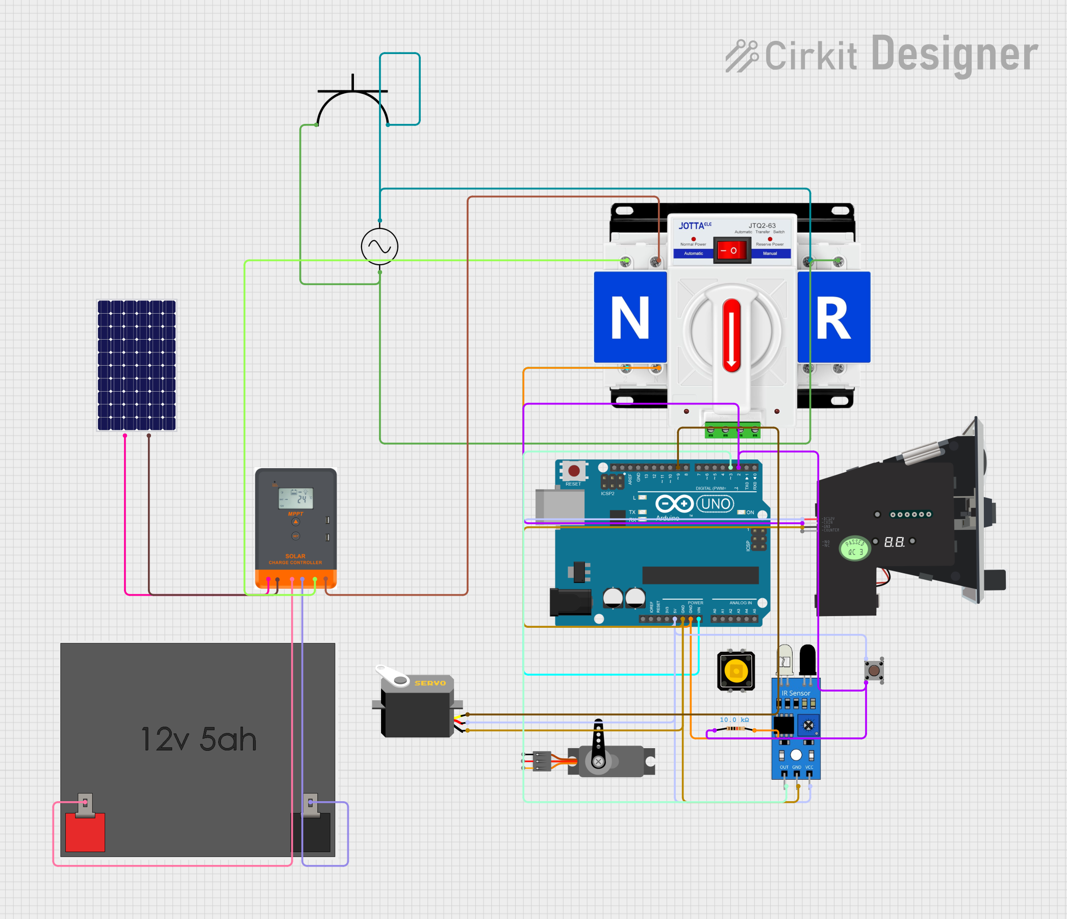
This circuit is designed to manage a solar-powered system with an automatic transfer switch, a coin acceptor, an IR sensor, and a servo motor controlled by an Arduino UNO. The system includes a solar panel, a solar charge controller, a 12V battery, and an AC power supply. The Arduino UNO is programmed to control the servo motor based on inputs from the coin acceptor and the IR sensor.
Component List
Solar Panel
- Pins: +, -
- Description: Converts sunlight into electrical energy.
- Purpose: Provides power to the solar charge controller.
Arduino UNO
- Pins: UNUSED, IOREF, Reset, 3.3V, 5V, GND, Vin, A0, A1, A2, A3, A4, A5, SCL, SDA, AREF, D13, D12, D11, D10, D9, D8, D7, D6, D5, D4, D3, D2, D1, D0
- Description: Microcontroller board.
- Purpose: Controls the servo motor and processes inputs from the coin acceptor and IR sensor.
Multi Coin Acceptor
- Pins: COIN, DC12V, GND, COUNTER
- Description: Accepts multiple types of coins.
- Purpose: Detects coin insertion and sends a signal to the Arduino.
Solar Charge Controller
- Pins: Solar +, Solar -, Battery +, Battery -, Load +, Load -
- Description: Manages the charging of the battery from the solar panel.
- Purpose: Ensures the battery is charged properly and provides power to the load.
12V 5Ah Battery
- Pins: 12v +, 12v -
- Description: Stores electrical energy.
- Purpose: Provides backup power to the system.
IR Sensor
- Pins: out, gnd, vcc
- Description: Detects objects using infrared light.
- Purpose: Detects the presence of an object to trigger the servo motor.
Servo
- Pins: GND, VCC, PWM
- Description: Rotational actuator.
- Purpose: Dispenses items based on signals from the Arduino.
AC Supply
- Pins: +ve, -ve
- Description: Provides AC power.
- Purpose: Supplies power to the automatic transfer switch.
AC Power Plug
- Pins: positive terminal, negative terminal
- Description: Connects to an AC power source.
- Purpose: Provides AC power to the system.
Dual Power Automatic Transfer Switch
- Pins: +, -
- Description: Switches between two power sources.
- Purpose: Automatically switches between solar and AC power.
Momentary Push Button Switch
- Pins: 1, 3, 2, 4
- Description: Momentary switch.
- Purpose: Provides a manual input to the system.
Resistor
- Pins: pin1, pin2
- Description: 10k Ohm resistor.
- Purpose: Limits current in the circuit.
Pushbutton
- Pins: Pin 3 (out), Pin 4 (out), Pin 1 (in), Pin 2 (in)
- Description: Pushbutton switch.
- Purpose: Provides a manual input to the system.
Wiring Details
Solar Panel
- + connected to Solar Charge Controller Solar +
- - connected to Solar Charge Controller Solar -
Arduino UNO
- 5V connected to Multi Coin Acceptor DC12V, Servo VCC, Pushbutton Pin 1 (in), IR Sensor vcc
- GND connected to Multi Coin Acceptor GND, Servo gnd, IR Sensor gnd, Dual Power Automatic Transfer Switch -
- Vin connected to Dual Power Automatic Transfer Switch +
- D9 connected to Servo pulse
- D3 connected to IR Sensor out
- D2 connected to Multi Coin Acceptor COIN, Pushbutton Pin 2 (in), Resistor pin1
Multi Coin Acceptor
- DC12V connected to Arduino UNO 5V
- GND connected to Arduino UNO GND
- COIN connected to Arduino UNO D2
Solar Charge Controller
- Solar + connected to Solar Panel +
- Solar - connected to Solar Panel -
- Battery + connected to 12V 5Ah Battery 12v +
- Battery - connected to 12V 5Ah Battery 12v -
- Load + connected to Dual Power Automatic Transfer Switch +
- Load - connected to Dual Power Automatic Transfer Switch -
12V 5Ah Battery
- 12v + connected to Solar Charge Controller Battery +
- 12v - connected to Solar Charge Controller Battery -
IR Sensor
- vcc connected to Arduino UNO 5V
- gnd connected to Arduino UNO GND
- out connected to Arduino UNO D3
Servo
- VCC connected to Arduino UNO 5V
- GND connected to Arduino UNO GND
- PWM connected to Arduino UNO D9
AC Supply
- +ve connected to Dual Power Automatic Transfer Switch +
- -ve connected to Dual Power Automatic Transfer Switch -
AC Power Plug
- positive terminal connected to AC Supply +ve
- negative terminal connected to AC Supply -ve
Dual Power Automatic Transfer Switch
- + connected to Arduino UNO Vin, Solar Charge Controller Load +, AC Supply +ve, AC Power Plug positive terminal
- - connected to Arduino UNO GND, Solar Charge Controller Load -, AC Supply -ve, AC Power Plug negative terminal
Momentary Push Button Switch
- Pin 1 (in) connected to Arduino UNO 5V
- Pin 2 (in) connected to Arduino UNO D2
- Pin 3 (out) not connected
- Pin 4 (out) not connected
Resistor
- pin1 connected to Arduino UNO D2
- pin2 connected to Dual Power Automatic Transfer Switch -
Pushbutton
- Pin 1 (in) connected to Arduino UNO 5V
- Pin 2 (in) connected to Arduino UNO D2
- Pin 3 (out) not connected
- Pin 4 (out) not connected
Documented Code
Arduino UNO Code
#include <Servo.h>

Servo myservo;
const int buttonPin = 2;
const int irPin = 3;
const int servoPin = 9;
int buttonState = 0;
int coinInserted = 0;

void setup() {
  pinMode(buttonPin, INPUT);
  pinMode(irPin, INPUT);
  myservo.attach(servoPin);
  myservo.write(0); // Initial position
  Serial.begin(9600);
}

void loop() {
  buttonState = digitalRead(buttonPin);

  if (buttonState == HIGH) {
    coinInserted = 1;
    Serial.println("Button Pressed (Coin Inserted)");
    delay(200); // Debounce delay to avoid multiple detections
  }

  if (coinInserted && digitalRead(irPin) == LOW) {
    Serial.println("Dispensing Mask");
    myservo.write(90); // Move servo to dispense mask
    delay(1000); // Wait for 1 second
    myservo.write(0); // Return servo to initial position
    coinInserted = 0; // Reset coin inserted flag
  }
}
12V 5Ah Battery Code
void setup() {
  // put your setup code here, to run once:
}

void loop() {
  // put your main code here, to run repeatedly:
}
This documentation provides a comprehensive overview of the circuit, including a summary, component list, wiring details, and documented code.