
Arduino Mega 2560 Controlled Multi-Stepper Motor System with OLED Display and Potentiometer Speed Control
View and Edit Project In Cirkit Designer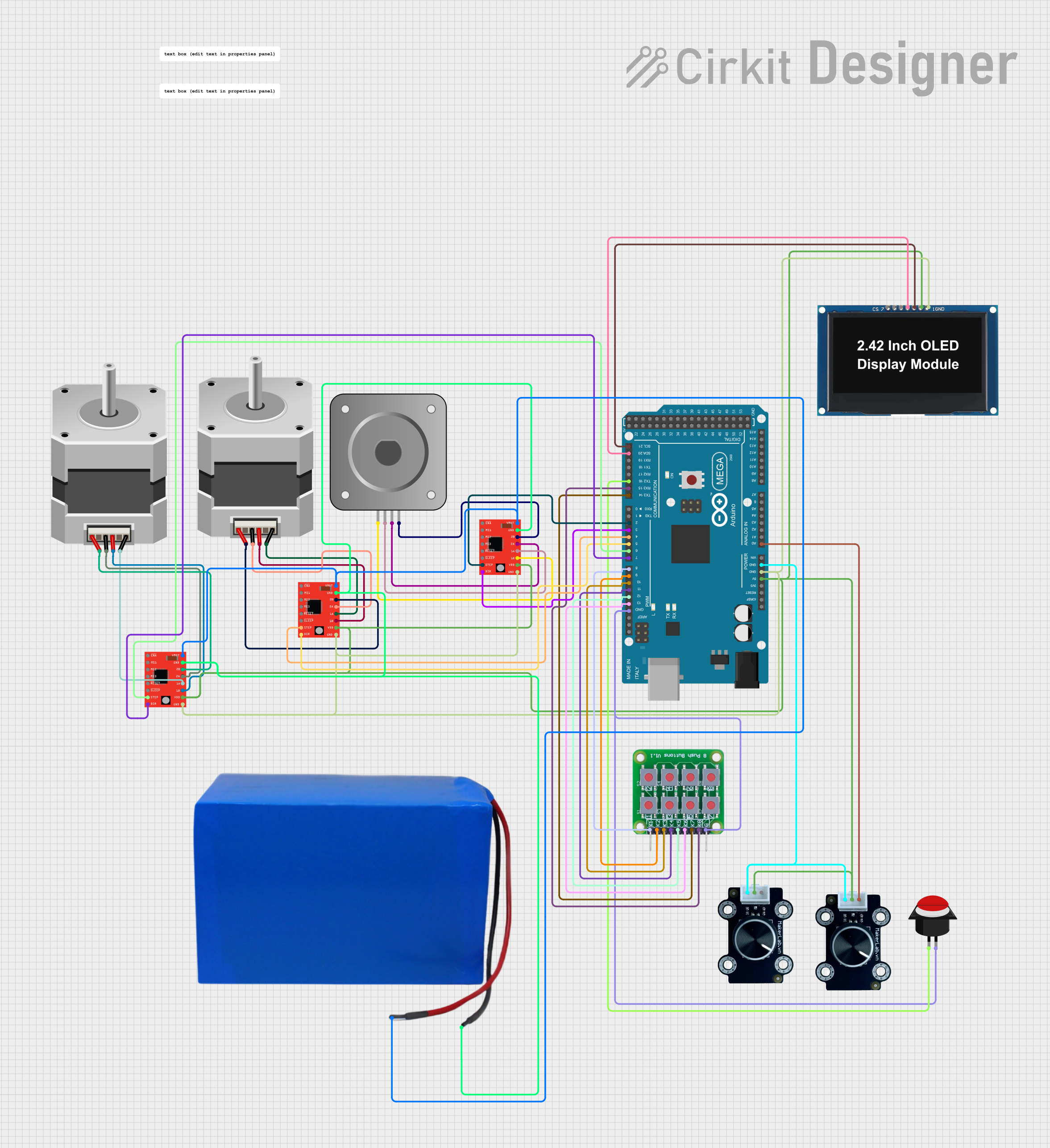
Circuit Documentation
Summary
This circuit controls a system with three stepper motors, eight push buttons, two potentiometers, and an OLED display. The system operates in three modes, each activated by a long press of a specific button. The potentiometers control the speed of the motors, and the OLED display shows relevant information such as speed in RPM, motor angles, and operation count. The circuit is managed by an Arduino Mega 2560 microcontroller.
Component List
Bipolar Stepper Motor (NEMA 17)
- Pins: A-, A+, B+, B-
- Description: A bipolar stepper motor used for precise control of rotational position.
Stepper Motor (Bipolar)
- Pins: D, B, C, A
- Description: A bipolar stepper motor used for precise control of rotational position.
A4988 Stepper Motor Driver (Red)
- Pins: ENABLE, MS1, MS2, MS3, RESET, SLEEP, STEP, DIR, VMOT, GND, 2B, 2A, 1A, 1B, VDD
- Description: A driver module for controlling bipolar stepper motors.
Arduino Mega 2560
- Pins: IOREF, RESET, 3V3, 5V, GND, VIN, A0-A15, D0-D53, AREF, SDA, SCL
- Description: A microcontroller board based on the ATmega2560.
8 Push Button Board PCB
- Pins: K1, K2, K3, K4, K5, K6, K7, K8, GROUND
- Description: A PCB with 8 push buttons for user input.
Push Button Round
- Pins: leg0, leg1
- Description: A single round push button for user input.
MKE-M04 Potentiometer Module
- Pins: GND, 5V, SIG
- Description: A potentiometer module for analog input.
OLED Display 2.42"
- Pins: GND, VCC, SCK, SDA, RES, DC, CS
- Description: An OLED display for visual output.
Battery 38.5V 24Ah
- Pins: Out +ve, Out -ve
- Description: A battery for powering the circuit.
Wiring Details
Bipolar Stepper Motor (NEMA 17)
- A- connected to 1B of A4988 Stepper Motor Driver (Red)
- A+ connected to 1A of A4988 Stepper Motor Driver (Red)
- B+ connected to 2A of A4988 Stepper Motor Driver (Red)
- B- connected to 2B of A4988 Stepper Motor Driver (Red)
Stepper Motor (Bipolar)
- D connected to 1A of A4988 Stepper Motor Driver (Red)
- B connected to 1B of A4988 Stepper Motor Driver (Red)
- C connected to 2A of A4988 Stepper Motor Driver (Red)
- A connected to 2B of A4988 Stepper Motor Driver (Red)
A4988 Stepper Motor Driver (Red)
- STEP connected to D4 PWM of Arduino Mega 2560
- DIR connected to D5 PWM of Arduino Mega 2560
- VMOT connected to Out +ve of Battery 38.5V 24Ah
- GND connected to Out -ve of Battery 38.5V 24Ah
- VDD connected to 5V of Arduino Mega 2560
Arduino Mega 2560
- D2 PWM connected to STEP of A4988 Stepper Motor Driver (Red)
- D3 PWM connected to DIR of A4988 Stepper Motor Driver (Red)
- D4 PWM connected to STEP of A4988 Stepper Motor Driver (Red)
- D5 PWM connected to DIR of A4988 Stepper Motor Driver (Red)
- D6 PWM connected to STEP of A4988 Stepper Motor Driver (Red)
- D7 PWM connected to DIR of A4988 Stepper Motor Driver (Red)
- D8 PWM connected to K1 of 8 Push Button Board PCB
- D9 PWM connected to K2 of 8 Push Button Board PCB
- D10 PWM connected to K3 of 8 Push Button Board PCB
- D11 PWM connected to K4 of 8 Push Button Board PCB
- D12 PWM connected to K5 of 8 Push Button Board PCB
- D13 PWM connected to K6 of 8 Push Button Board PCB
- D14/TX3 connected to K7 of 8 Push Button Board PCB
- D15/RX3 connected to K8 of 8 Push Button Board PCB
- D16 PWM/TX2 connected to leg0 of Push Button Round
- A0 connected to SIG of MKE-M04 Potentiometer Module
- D21/SCL connected to SCK of OLED Display 2.42"
- D20/SDA connected to SDA of OLED Display 2.42"
- 5V connected to VCC of OLED Display 2.42"
- GND connected to GND of OLED Display 2.42"
8 Push Button Board PCB
- K1 connected to D8 PWM of Arduino Mega 2560
- K2 connected to D9 PWM of Arduino Mega 2560
- K3 connected to D10 PWM of Arduino Mega 2560
- K4 connected to D11 PWM of Arduino Mega 2560
- K5 connected to D12 PWM of Arduino Mega 2560
- K6 connected to D13 PWM of Arduino Mega 2560
- K7 connected to D14/TX3 of Arduino Mega 2560
- K8 connected to D15/RX3 of Arduino Mega 2560
- GROUND connected to GND of Arduino Mega 2560
Push Button Round
- leg0 connected to D16 PWM/TX2 of Arduino Mega 2560
- leg1 connected to GROUND of 8 Push Button Board PCB
MKE-M04 Potentiometer Module
- GND connected to GND of Arduino Mega 2560
- 5V connected to 5V of Arduino Mega 2560
- SIG connected to A0 of Arduino Mega 2560
OLED Display 2.42"
- GND connected to GND of Arduino Mega 2560
- VCC connected to 5V of Arduino Mega 2560
- SCK connected to D21/SCL of Arduino Mega 2560
- SDA connected to D20/SDA of Arduino Mega 2560
Battery 38.5V 24Ah
- Out +ve connected to VMOT of A4988 Stepper Motor Driver (Red)
- Out -ve connected to GND of A4988 Stepper Motor Driver (Red)
Code Documentation
/*
 * This Arduino sketch controls a system with 3 stepper motors, 8 push buttons,
 * 2 potentiometers, and an OLED display. The system has 3 modes of operation,
 * each activated by a long press of a specific button. The potentiometers are
 * used to control the speed of the motors, and the OLED display shows relevant
 * information such as speed in RPM, motor angles, and operation count.
 */

#include <AccelStepper.h>
#include <Wire.h>
#include <Adafruit_GFX.h>
#include <Adafruit_SSD1306.h>

#define SCREEN_WIDTH 128
#define SCREEN_HEIGHT 64
#define OLED_RESET -1
Adafruit_SSD1306 display(SCREEN_WIDTH, SCREEN_HEIGHT, &Wire, OLED_RESET);

// Define stepper motor connections and interface type
AccelStepper stepper1(AccelStepper::DRIVER, 2, 3);
AccelStepper stepper2(AccelStepper::DRIVER, 4, 5);
AccelStepper stepper3(AccelStepper::DRIVER, 6, 7);

// Define button pins
const int buttonPins[8] = {8, 9, 10,