Arduino UNO Controlled Environment Monitoring and Response System
Circuit Documentation
Summary
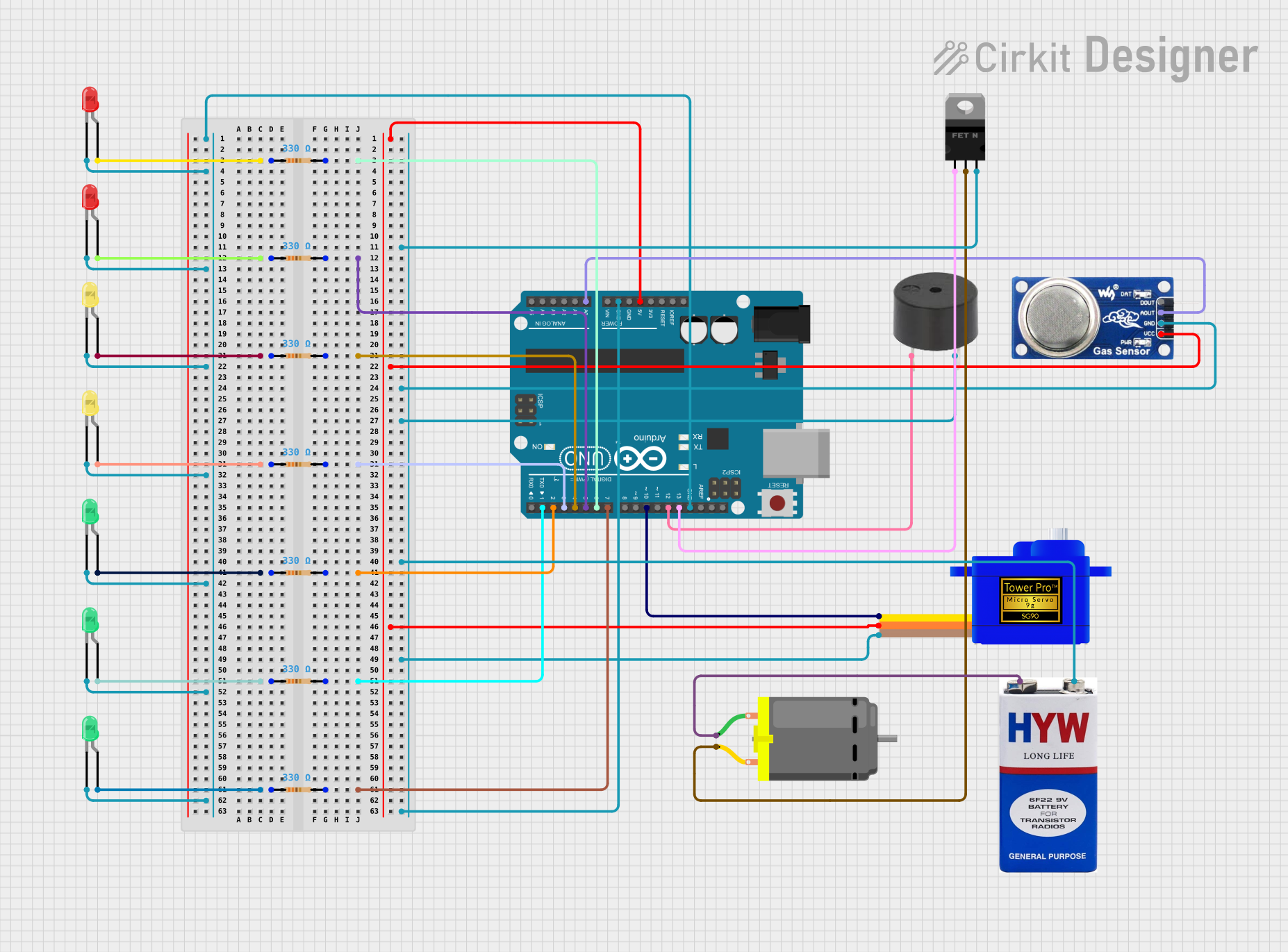
This circuit is designed to interface with various components including LEDs, a servomotor, a buzzer, an MQ6 gas sensor, resistors, a MOSFET, a DC motor, and a 9V battery, all controlled by an Arduino UNO microcontroller. The circuit appears to be a multi-functional system capable of driving LEDs, a motor, and a servomotor, as well as reading from a gas sensor and sounding a buzzer. The LEDs are connected through resistors to the digital pins of the Arduino for controlled lighting. The servomotor and buzzer are also connected to the Arduino for operation. The MOSFET is used to control the DC motor with a 9V battery as the power source. The MQ6 gas sensor's analog output is connected to the Arduino for gas detection.
Component List
Servomotor SG90
- Description: A small and lightweight servo used for things like simple robotics.
- Pins: SIG (Signal), VCC (Power), GND (Ground)
LEDs (Red, Yellow, Green)
- Description: Light Emitting Diodes of various colors used as indicators.
- Pins: Anode (+), Cathode (-)
Buzzer
- Description: An electronic buzzer for audible alerts.
- Pins: PIN (Signal), GND (Ground)
MQ6 Gas Sensor
- Description: A gas sensor for detecting LPG, butane, propane, methane, alcohol, hydrogen, and smoke.
- Pins: VCC (Power), GND (Ground), A0 (Analog Output), DO (Digital Output)
Resistors (330 Ohms)
- Description: Resistors used to limit current to LEDs and possibly other components.
- Pins: Pin1, Pin2
Arduino UNO
- Description: A microcontroller board based on the ATmega328P.
- Pins: Various digital and analog I/O, power, and ground pins.
nMOS Transistor (MOSFET)
- Description: A type of field-effect transistor used for switching electronic signals.
- Pins: Gate, Drain, Source
DC Motor
- Description: A motor that runs on direct current electricity.
- Pins: Pin 1, Pin 2
9V Battery
- Description: A standard 9V battery used as a power source.
- Pins: + (Positive), - (Negative)
Wiring Details
Servomotor SG90
- VCC connected to Arduino's 5V
- GND connected to common ground
- SIG connected to Arduino's D10
LEDs (Red, Yellow, Green)
- Anode connected to one end of a 330 Ohm resistor
- Cathode connected to common ground
Buzzer
- PIN connected to Arduino's D12
- GND connected to common ground
MQ6 Gas Sensor
- VCC connected to Arduino's 5V
- GND connected to common ground
- A0 connected to Arduino's A0
Resistors (330 Ohms)
- One end connected to an LED anode
- Other end connected to a digital pin on the Arduino (D2, D3, D4, D5, D6, D7, D1)
Arduino UNO
- Controls LEDs, servomotor, buzzer, and reads from the MQ6 sensor
- Digital and analog pins connected as per wiring details
nMOS Transistor (MOSFET)
- Gate connected to Arduino's D13
- Drain connected to DC Motor's pin 2
- Source connected to common ground
DC Motor
- Pin 1 connected to 9V battery +
- Pin 2 connected to MOSFET's drain
9V Battery
- connected to DC Motor's pin 1
- connected to common ground
Documented Code
Arduino UNO Code (sketch.ino)
void setup() {
  // put your setup code here, to run once:

}

void loop() {
  // put your main code here, to run repeatedly:

}
Additional Notes (documentation.txt)
No additional code documentation provided.