
Circuit Documentation
Summary of the Circuit
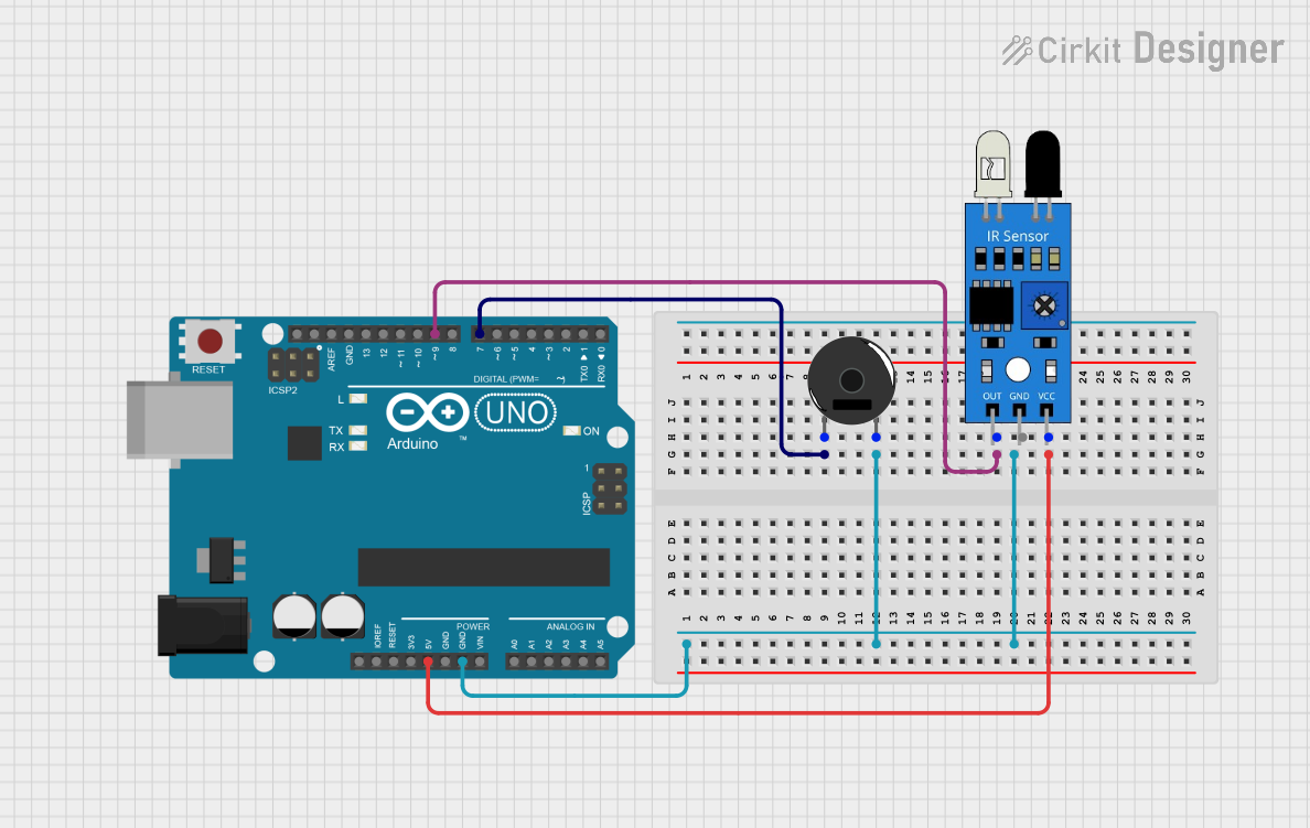
This circuit consists of an Arduino UNO microcontroller, a Piezo Buzzer, and an IR sensor. The Arduino UNO serves as the central processing unit, controlling the behavior of the Piezo Buzzer based on the input from the IR sensor. The IR sensor detects infrared signals and sends the data to the Arduino UNO, which then decides whether to activate the Piezo Buzzer. The circuit is powered by the Arduino UNO's 5V output, and the ground connections are shared among the components.
Component List
Arduino UNO
- Description: A microcontroller board based on the ATmega328P.
- Purpose: Acts as the central processing unit for the circuit, reading sensor inputs and driving the Piezo Buzzer.
- Pins: UNUSED, IOREF, Reset, 3.3V, 5V, GND, Vin, A0-A5, SCL, SDA, AREF, D0-D13.
Piezo Buzzer
- Description: An electronic device that emits sound when an electrical signal is applied.
- Purpose: Produces an audible alert when triggered by the Arduino UNO.
- Pins: pin 1, pin 2.
IR Sensor
- Description: A sensor that detects infrared light, commonly used in proximity and object detection.
- Purpose: Senses the presence of objects or motion and sends a signal to the Arduino UNO.
- Pins: out, gnd, vcc.
Wiring Details
Arduino UNO
- GND connected to Piezo Buzzer pin 2 and IR Sensor gnd.
- D7 connected to Piezo Buzzer pin 1.
- D9 connected to IR Sensor out.
- 5V connected to IR Sensor vcc.
Piezo Buzzer
- pin 1 connected to Arduino UNO D7.
- pin 2 connected to Arduino UNO GND.
IR Sensor
- out connected to Arduino UNO D9.
- gnd connected to Arduino UNO GND.
- vcc connected to Arduino UNO 5V.
Documented Code
Arduino UNO Code (sketch.ino)
void setup() {
  // put your setup code here, to run once:

}

void loop() {
  // put your main code here, to run repeatedly:

}
Additional Notes (documentation.txt)
No additional code documentation provided.