
Arduino UNO-Based Environmental Monitoring System with Multiple Sensors
View and Edit Project In Cirkit Designer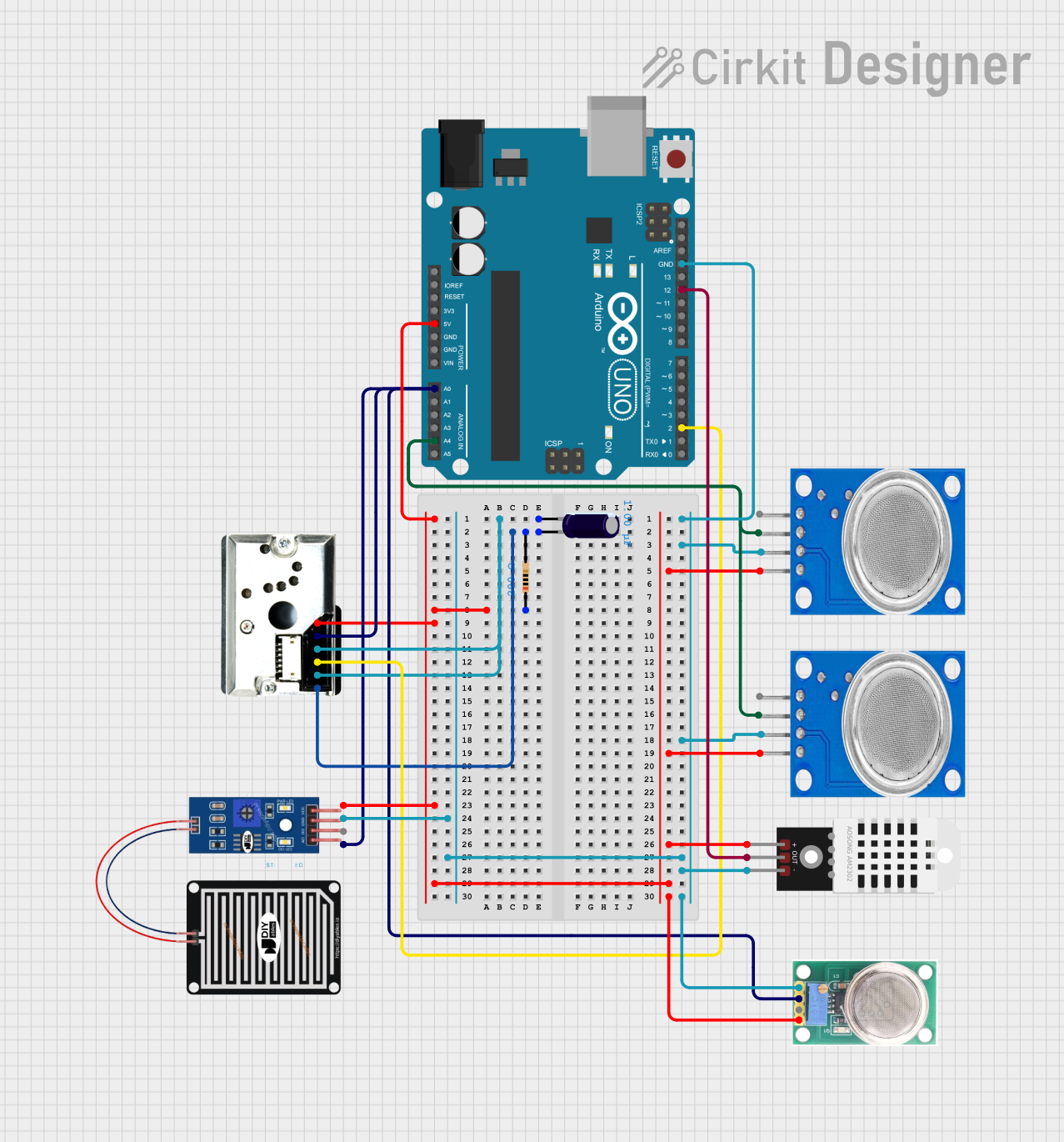
Circuit Documentation
Summary
This document provides a detailed overview of a circuit that includes an Arduino UNO microcontroller, various sensors, and other components. The circuit is designed to interface with multiple sensors to collect environmental data and process it using the Arduino UNO. The sensors include a dust sensor (GP2Y1010AU0F), gas sensors (MQ135 and MQ-136), a rain sensor, and a temperature and humidity sensor (DHT22). The circuit also includes passive components like a resistor and an electrolytic capacitor.
Component List
Arduino UNO
- Description: A microcontroller board based on the ATmega328P.
- Pins: UNUSED, IOREF, Reset, 3.3V, 5V, GND, Vin, A0, A1, A2, A3, A4, A5, SCL, SDA, AREF, D13, D12, D11, D10, D9, D8, D7, D6, D5, D4, D3, D2, D1, D0
GP2Y1010AU0F
- Description: An optical air quality sensor.
- Pins: VCC, Vout, S-GND, LED, LED-GND, V-LED
Electrolytic Capacitor
- Description: A capacitor used for filtering and smoothing.
- Pins: -, +
- Properties:
- Capacitance: 0.000001 Farads
Resistor
- Description: A resistor used for current limiting.
- Pins: pin1, pin2
- Properties:
- Resistance: 200 Ohms
MQ135
- Description: A gas sensor for detecting air quality.
- Pins: VCC, GND, A0, D0
MQ-136
- Description: A gas sensor for detecting sulfur hexafluoride (SF6).
- Pins: GND, OUT1, OUT2, VCC
RAIN SENSOR
- Description: A sensor for detecting rain.
- Pins: AO, DO, GRD, VCC
DHT22
- Description: A temperature and humidity sensor.
- Pins: +, Out, -
Wiring Details
Arduino UNO
- 5V: Connected to pin1 of the Resistor.
- GND: Connected to GND of MQ135, GND of MQ135, - of DHT22, GND of MQ-136, and GRD of RAIN SENSOR.
- A0: Connected to AO of RAIN SENSOR, OUT1 of MQ-136, and Vout of GP2Y1010AU0F.
- A4: Connected to A0 of MQ135 and A0 of MQ135.
- D12: Connected to Out of DHT22.
- D2: Connected to LED of GP2Y1010AU0F.
GP2Y1010AU0F
- VCC: Connected to pin1 of the Resistor.
- Vout: Connected to A0 of Arduino UNO.
- S-GND: Connected to - of Electrolytic Capacitor.
- LED: Connected to D2 of Arduino UNO.
- LED-GND: Connected to - of Electrolytic Capacitor.
- V-LED: Connected to pin2 of the Resistor.
Electrolytic Capacitor
- -: Connected to S-GND and LED-GND of GP2Y1010AU0F.
- +: Connected to pin2 of the Resistor and V-LED of GP2Y1010AU0F.
Resistor
- pin1: Connected to 5V of Arduino UNO and VCC of GP2Y1010AU0F, VCC of RAIN SENSOR, VCC of MQ135, VCC of MQ135, + of DHT22, and VCC of MQ-136.
- pin2: Connected to + of Electrolytic Capacitor and V-LED of GP2Y1010AU0F.
MQ135
- VCC: Connected to pin1 of the Resistor.
- GND: Connected to GND of Arduino UNO.
- A0: Connected to A4 of Arduino UNO.
- D0: Not connected.
MQ-136
- GND: Connected to GND of Arduino UNO.
- OUT1: Connected to A0 of Arduino UNO.
- OUT2: Not connected.
- VCC: Connected to pin1 of the Resistor.
RAIN SENSOR
- AO: Connected to A0 of Arduino UNO.
- DO: Not connected.
- GRD: Connected to GND of Arduino UNO.
- VCC: Connected to pin1 of the Resistor.
DHT22
- +: Connected to pin1 of the Resistor.
- Out: Connected to D12 of Arduino UNO.
- -: Connected to GND of Arduino UNO.
Documented Code
Arduino UNO Code (sketch.ino)
void setup() {
  // put your setup code here, to run once:

}

void loop() {
  // put your main code here, to run repeatedly:

}
Additional Documentation (documentation.txt)
This document provides a comprehensive overview of the circuit, including a summary, component list, wiring details, and documented code. Each component is described, and its connections are detailed to ensure clarity and ease of understanding.