
ESP32-Based Environmental Data Logger with GPS and RF Communication
View and Edit Project In Cirkit Designer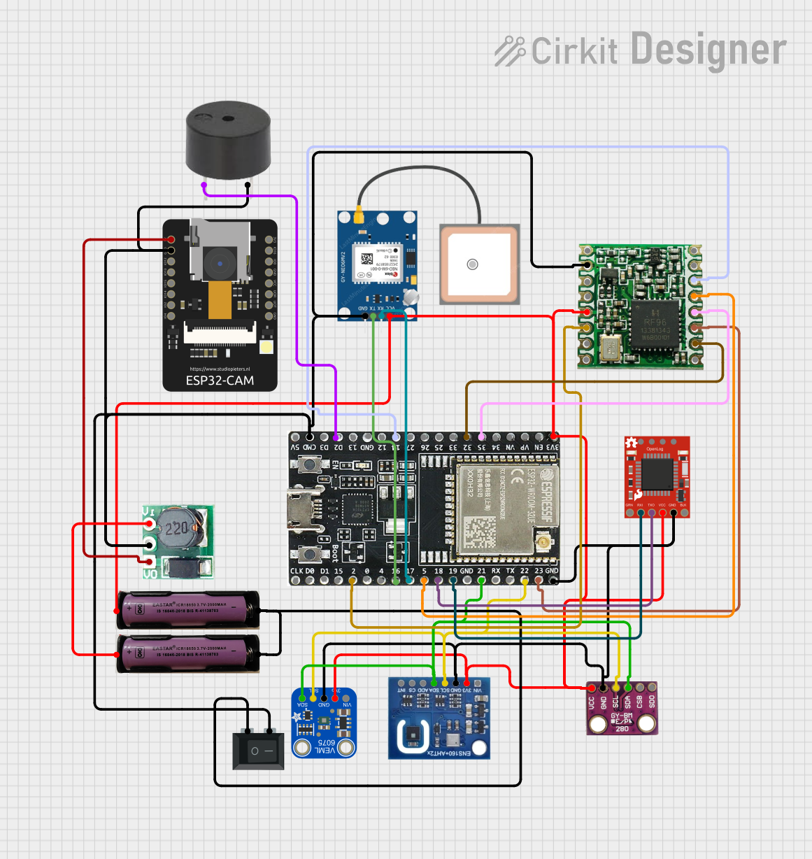
Circuit Documentation
Summary
The circuit is designed to collect environmental data using various sensors, including temperature, pressure, altitude, UV levels, air quality, and GPS location. The data is logged to an SD card through the SparkFun OpenLog. The ESP32-WROOM-32UE microcontroller serves as the central processing unit, interfacing with the BMP280, Adafruit VEML6075 UV Sensor, ENS160+AHT21 air quality sensor, and GPS NEO 6M module. A step-up boost converter is used to power the ESP32-CAM module, and a buzzer is included for audio feedback. The circuit is powered by a 3.7V battery, and a rocker switch is used to control power to the circuit.
Component List
- 3.7V Battery: Provides power to the circuit.
- BMP280: A sensor for measuring temperature, pressure, and altitude.
- SparkFun OpenLog: An open-source data logger that records incoming serial data to a microSD card.
- ESP32-WROOM-32UE: A powerful microcontroller with Wi-Fi and Bluetooth capabilities.
- Adafruit VEML6075 UV Sensor Breakout: Measures UVA and UVB light to calculate the UV index.
- GPS NEO 6M: A GPS module for location tracking.
- Step Up Boost 3V to 5V: Boosts the voltage from 3.7V to 5V to power components requiring 5V.
- ENS160+AHT21: A sensor for measuring air quality (TVOC and eCO2) and humidity.
- Rocker Switch (SPST): A single-pole single-throw switch to control the power supply.
- ESP32-CAM: A small camera module with Wi-Fi capabilities.
- RFM95: A LoRa transceiver module for long-range communication.
- Buzzer: Provides audio feedback.
Wiring Details
Power Supply
- 3.7V Battery is connected to the
3v3pins of the ESP32-WROOM-32UE, GPS NEO 6M, BMP280, ENS160+AHT21, SparkFun OpenLog, RFM95, and Adafruit VEML6075 UV Sensor. - Step Up Boost 3V to 5V takes input from the 3.7V battery and outputs to the
5Vpin of the ESP32-CAM.
Ground Connections
- The
GNDpins of all components are interconnected, forming a common ground.
Sensor Data Lines
- BMP280, ENS160+AHT21, and Adafruit VEML6075 UV Sensor are connected to the ESP32-WROOM-32UE via I2C with
SDAto pin21andSCLto pin22.
Serial Communication
- SparkFun OpenLog is connected to the ESP32-WROOM-32UE with
RXIto pin19andTXOto pin18. - GPS NEO 6M is connected to the ESP32-WROOM-32UE with
RXto pin17andTXto pin16.
RFM95 LoRa Module
- Connected to the ESP32-WROOM-32UE with
SCKto pin35,MISOto pin32,MOSIto pin23,NSSto pin5,RESETto pin14, andDIO0to pin2.
Buzzer
- Connected to the ESP32-WROOM-32UE with
PINto pinD2.
Power Control
- Rocker Switch (SPST) is used to control the connection between the 3.7V battery's negative terminal and the circuit's common ground.
Documented Code
/*
 * This Arduino Sketch reads data from BMP280, Adafruit VEML6075 UV Sensor,
 * ENS160+AHT21, and GPS NEO 6M sensors and logs the data to an SD card
 * using the SparkFun OpenLog.
 */

#include <Wire.h>
#include <Adafruit_Sensor.h>
#include <Adafruit_BMP280.h>
#include <Adafruit_VEML6075.h>
#include <SparkFunENS160.h>
#include <TinyGPS++.h>

// Sensor objects
Adafruit_BMP280 bmp;
Adafruit_VEML6075 uv = Adafruit_VEML6075();
ENS160 airQuality;
TinyGPSPlus gps;

// OpenLog Serial
#define OPENLOG_RX 21
#define OPENLOG_TX 19

void setup() {
  Serial.begin(115200);
  Serial2.begin(9600, SERIAL_8N1, OPENLOG_RX, OPENLOG_TX);
  Wire.begin();

  // Initialize BMP280
  if (!bmp.begin()) {
    Serial.println(F("Could not find a valid BMP280 sensor, check wiring!"));
    while (1);
  }

  // Initialize VEML6075
  if (!uv.begin()) {
    Serial.println(F("Failed to communicate with VEML6075 sensor, check wiring!"));
    while (1);
  }

  // Initialize ENS160
  if (!airQuality.begin()) {
    Serial.println(F("Failed to communicate with ENS160 sensor, check wiring!"));
    while (1);
  }

  // Initialize GPS
  Serial1.begin(9600, SERIAL_8N1, 17, 16);
}

void loop() {
  // Read BMP280 data
  float temperature = bmp.readTemperature();
  float pressure = bmp.readPressure();
  float altitude = bmp.readAltitude(1013.25);

  // Read VEML6075 data
  float uva = uv.readUVA();
  float uvb = uv.readUVB();
  float uvIndex = uv.readUVI();

  // Read ENS160 data
  airQuality.readData();
  int tvoc = airQuality.getTVOC();
  int eco2 = airQuality.getECO2();

  // Read GPS data
  while (Serial1.available() > 0) {
    gps.encode(Serial1.read());
  }
  float latitude = gps.location.lat();
  float longitude = gps.location.lng();
  float speed = gps.speed.kmph();

  // Log data to OpenLog
  Serial2.print("Temperature: "); Serial2.print(temperature); Serial2.print(" C, ");
  Serial2.print("Pressure: "); Serial2.print(pressure); Serial2.print(" Pa, ");
  Serial2.print("Altitude: "); Serial2.print(altitude); Serial2.print(" m, ");
  Serial2.print("UVA: "); Serial2.print(uva); Serial2.print(", UVB: ");
  Serial2.print(uvb); Serial2.print(", UV Index: "); Serial2.print(uvIndex); Serial2.print(", ");
  Serial2.print("TVOC: "); Serial2.print(tvoc); Serial2.print(" ppb, ");
  Serial2.print("eCO2: "); Serial2.print(eco2); Serial2.print(" ppm, ");
  Serial2.print("Latitude: "); Serial2.print(latitude, 6); Serial2.print(", Longitude: ");
  Serial2.print(longitude, 6); Serial2.print(", Speed: "); Serial2.print(speed); Serial2.println(" km/h");

  delay(1000); // Log data every second
}
This code is designed to run on the ESP32-WROOM-32UE microcontroller. It initializes the connected sensors, reads their data, and logs the information to an SD card using the SparkFun OpenLog. The GPS data is read from a separate serial port (Serial1) and the data logging is done over another serial port (Serial2) dedicated to the OpenLog.