
Arduino-Based Obstacle Avoiding and Line Following Robot with IR and Ultrasonic Sensors
View and Edit Project In Cirkit Designer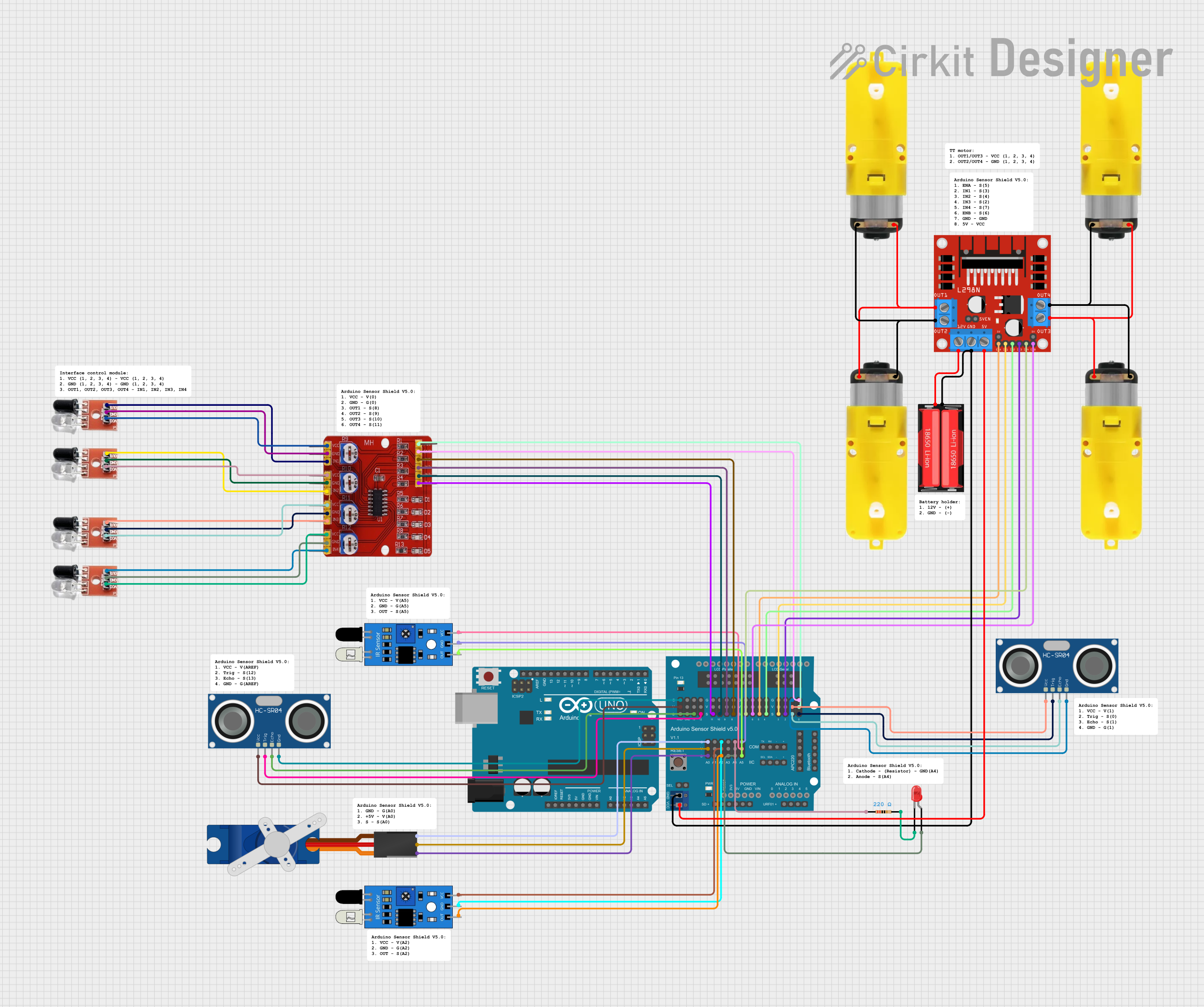
Circuit Documentation
Summary
This document provides a detailed overview of a circuit that includes various sensors, a motor driver, and an Arduino microcontroller. The circuit is designed to interface with multiple sensors and control motors, making it suitable for applications such as obstacle avoidance and line following in robotics.
Component List
4 Channel Infrared Tracing Module
- Pins: VCC, GND, IN1, IN2, IN3, IN4
- Description: Used for line following applications.
IR Sensor Avoid Obstacles
- Pins: VCC, GND, OUT
- Description: Used for obstacle detection.
HC-SR04 Ultrasonic Sensor
- Pins: VCC, TRIG, ECHO, GND
- Description: Used for distance measurement.
LED: Two Pin (red)
- Pins: Cathode, Anode
- Description: Used as an indicator.
Resistor
- Pins: Pin1, Pin2
- Description: 220 Ohms resistor used for current limiting.
L298N DC Motor Driver
- Pins: OUT1, OUT2, 12V, GND, 5V, OUT3, OUT4, 5V-ENA-JMP-I, 5V-ENA-JMP-O, +5V-J1, +5V-J2, ENA, IN1, IN2, IN3, IN4, ENB
- Description: Used to drive DC motors.
Arduino Sensor Shield v5.0
- Pins: Multiple pins for various sensors and actuators.
- Description: Provides easy connections for sensors and actuators to the Arduino.
Arduino UNO
- Pins: Multiple pins for I/O operations.
- Description: Microcontroller used to control the circuit.
Motor with Reducer
- Pins: 3 - 6 VCC, GND
- Description: DC motor with a gear reducer.
18650 Li-Ion
- Pins: Positive, Negative
- Description: Power source for the circuit.
Tower Pro SG90 Servo
- Pins: Signal, +5V, GND
- Description: Servo motor for precise control.
Wiring Details
4 Channel Infrared Tracing Module
- VCC connected to Arduino Sensor Shield v5.0 VCC (0-V)
- GND connected to Arduino Sensor Shield v5.0 GND (0-G)
- IN1 connected to Arduino Sensor Shield v5.0 (8-S)
- IN2 connected to Arduino Sensor Shield v5.0 (9-S)
- IN3 connected to Arduino Sensor Shield v5.0 (10-S)
- IN4 connected to Arduino Sensor Shield v5.0 (11-S)
IR Sensor Avoid Obstacles
- VCC connected to 4 Channel Infrared Tracing Module VCC
- GND connected to 4 Channel Infrared Tracing Module GND
- OUT connected to 4 Channel Infrared Tracing Module IN1, IN2, IN3, IN4
HC-SR04 Ultrasonic Sensor
- VCC connected to Arduino Sensor Shield v5.0 (AREF-V)
- GND connected to Arduino Sensor Shield v5.0 (AREF-G)
- TRIG connected to Arduino Sensor Shield v5.0 (12-S)
- ECHO connected to Arduino Sensor Shield v5.0 (13-S)
LED: Two Pin (red)
- Anode connected to Arduino Sensor Shield v5.0 (A4-SIG)
- Cathode connected to Resistor Pin2
Resistor
- Pin1 connected to Arduino Sensor Shield v5.0 (A4-GND)
- Pin2 connected to LED Cathode
L298N DC Motor Driver
- 5V connected to Arduino Sensor Shield v5.0 VCC
- GND connected to 18650 Li-Ion Negative, Arduino Sensor Shield v5.0 GND
- 12V connected to 18650 Li-Ion Positive
- IN1 connected to Arduino Sensor Shield v5.0 (3-S)
- IN2 connected to Arduino Sensor Shield v5.0 (4-S)
- IN3 connected to Arduino Sensor Shield v5.0 (2-S)
- IN4 connected to Arduino Sensor Shield v5.0 (7-S)
- ENA connected to Arduino Sensor Shield v5.0 (5-S)
- ENB connected to Arduino Sensor Shield v5.0 (6-S)
- OUT1 connected to Motor with Reducer VCC
- OUT2 connected to Motor with Reducer GND
- OUT3 connected to Motor with Reducer VCC
- OUT4 connected to Motor with Reducer GND
Arduino Sensor Shield v5.0
- VCC connected to L298N DC Motor Driver 5V
- GND connected to L298N DC Motor Driver GND, 18650 Li-Ion Negative
Arduino UNO
- Connected to Arduino Sensor Shield v5.0
Motor with Reducer
- VCC connected to L298N DC Motor Driver OUT1, OUT3
- GND connected to L298N DC Motor Driver OUT2, OUT4
18650 Li-Ion
- Positive connected to L298N DC Motor Driver 12V
- Negative connected to L298N DC Motor Driver GND, Arduino Sensor Shield v5.0 GND
Tower Pro SG90 Servo
- Signal connected to Arduino Sensor Shield v5.0 (A0-SIG)
- +5V connected to Arduino Sensor Shield v5.0 (A0-VCC)
- GND connected to Arduino Sensor Shield v5.0 (A0-GND)
Documented Code
Arduino UNO Code (sketch.ino)
void setup() {
  // put your setup code here, to run once:

}

void loop() {
  // put your main code here, to run repeatedly:

}
Additional Documentation (documentation.txt)
This documentation provides a comprehensive overview of the circuit, including the components used, their wiring details, and the code for the Arduino microcontroller.