Battery-Powered LED Control Circuit with Push Buttons and NPN Transistors
Circuit Documentation
Summary
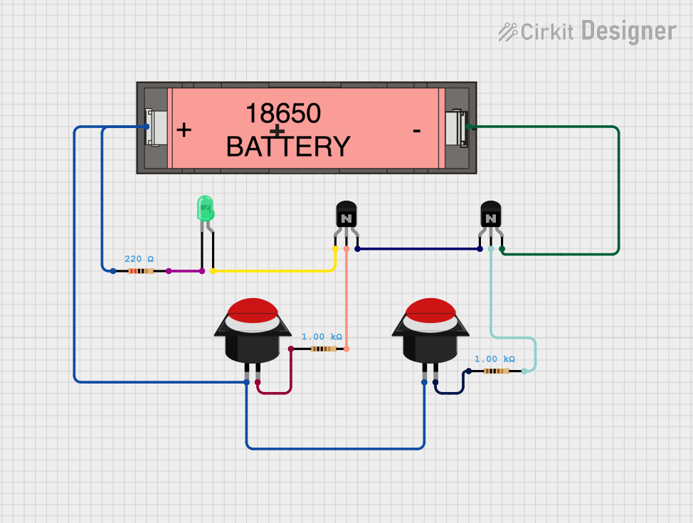
This circuit consists of various components including resistors, transistors, push buttons, an LED, and a Li-ion battery. The circuit is designed to control the LED using push buttons and transistors, with resistors used for current limiting and biasing.
Component List
Resistor (220 Ohms)
- Pins: pin1, pin2
- Description: Current limiting resistor
Resistor (1000 Ohms)
- Pins: pin1, pin2
- Description: Used for biasing transistors
NPN Transistor (CBE)
- Pins: collector, base, emitter
- Description: Used for switching
Push Button Round
- Pins: leg0, leg1
- Description: Used for user input
Li-ion 18650 Battery
- Pins: +, -
- Description: Power source
LED: Two Pin (green)
- Pins: cathode, anode
- Description: Visual indicator
Wiring Details
Resistor (220 Ohms)
pin1 is connected to:
- Li-ion 18650 Battery (+)
- Push Button Round (leg0)
- Push Button Round (leg0)
pin2 is connected to:
- LED: Two Pin (green) (cathode)
Resistor (1000 Ohms)
pin1 is connected to:
- Push Button Round (leg1)
pin2 is connected to:
- NPN Transistor (CBE) (base)
NPN Transistor (CBE)
collector is connected to:
- LED: Two Pin (green) (anode)
base is connected to:
- Resistor (1000 Ohms) (pin2)
emitter is connected to:
- NPN Transistor (CBE) (collector)
Push Button Round
leg0 is connected to:
- Resistor (220 Ohms) (pin1)
- Li-ion 18650 Battery (+)
- Push Button Round (leg0)
leg1 is connected to:
- Resistor (1000 Ohms) (pin1)
Li-ion 18650 Battery
+ is connected to:
- Resistor (220 Ohms) (pin1)
- Push Button Round (leg0)
- Push Button Round (leg0)
- is connected to:
- NPN Transistor (CBE) (emitter)
LED: Two Pin (green)
cathode is connected to:
- Resistor (220 Ohms) (pin2)
anode is connected to:
- NPN Transistor (CBE) (collector)
Code
No microcontroller code is provided for this circuit.
This documentation provides a detailed overview of the components and their connections within the circuit. Each component is listed with its respective pins and connections to ensure clarity in the circuit design.