Battery-Powered Rain Sensor with Buzzer Alert and Relay Control
Circuit Documentation
Summary
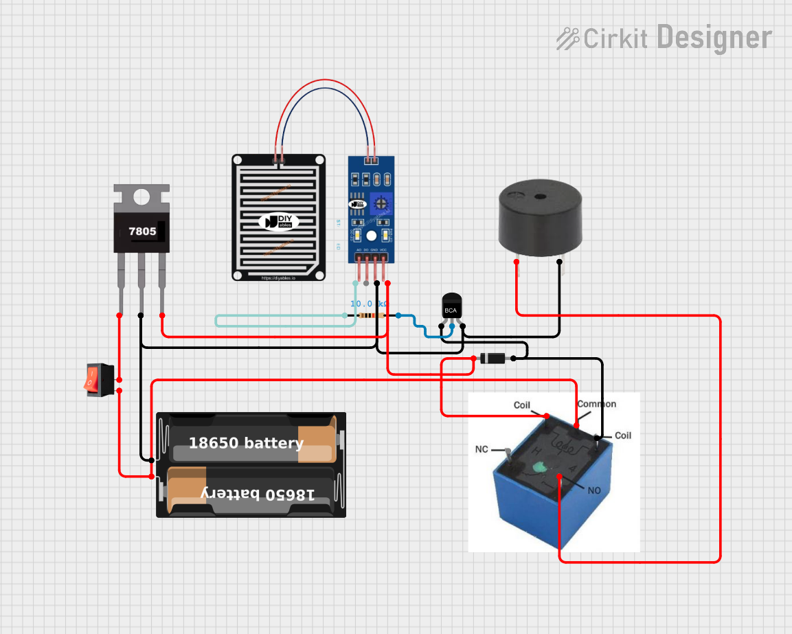
This document provides a detailed overview of a circuit that includes a variety of components such as a rocker switch, rain sensor, NPN transistor, diodes, a 5V relay, a battery case, a 7805 voltage regulator, a buzzer, and a resistor. The circuit is designed to monitor rain and activate a buzzer through a series of interconnected components.
Component List
Rocker Switch
- Description: A switch that can toggle between on and off states.
- Pins:
input,output
Rain Sensor
- Description: A sensor that detects the presence of rain.
- Pins:
AO,DO,GRD,VCC
NPN Transistor
- Description: A transistor used for switching and amplification.
- Pins:
E,C,B
Diode
- Description: A component that allows current to flow in one direction only.
- Pins:
cathode,anode
5V Relay
- Description: An electromechanical switch that is activated by a 5V signal.
- Pins: (Not specified)
Battery Case
- Description: A case that holds batteries to provide power to the circuit.
- Pins:
+,-
7805 Voltage Regulator
- Description: A voltage regulator that outputs a stable 5V.
- Pins:
Vin,Gnd,Vout
Buzzer
- Description: A component that produces sound when activated.
- Pins:
PIN,GND
Resistor
- Description: A component that resists the flow of current.
- Pins:
pin1,pin2 - Properties:
- Resistance: 10,000 Ohms
Wiring Details
Rocker Switch
- input is connected to the
+pin of the Battery Case. - output is connected to the
Vinpin of the 7805 Voltage Regulator.
Rain Sensor
- GRD is connected to the
-pin of the Battery Case. - VCC is connected to the
cathodepin of the Diode. - AO is connected to
pin1of the Resistor.
NPN Transistor
- B is connected to the
Gndpin of the 7805 Voltage Regulator. - E is connected to the
anodepin of the Diode. - C is connected to
pin2of the Resistor.
Diode (Instance 1)
- cathode is connected to the
Voutpin of the 7805 Voltage Regulator. - anode is connected to the
Epin of the NPN Transistor.
Diode (Instance 2)
- cathode is connected to the
Voutpin of the 7805 Voltage Regulator. - anode is connected to the
Epin of the NPN Transistor.
5V Relay
- Connected to the
+pin of the Battery Case. - Connected to the
Voutpin of the 7805 Voltage Regulator. - Connected to the
anodepin of the Diode. - Connected to the
PINpin of the Buzzer.
Battery Case
- + is connected to the
inputpin of the Rocker Switch. - - is connected to the
GNDpin of the Buzzer. - - is connected to the
Gndpin of the 7805 Voltage Regulator. - - is connected to the
Bpin of the NPN Transistor. - - is connected to the
GRDpin of the Rain Sensor.
7805 Voltage Regulator
- Vin is connected to the
outputpin of the Rocker Switch. - Gnd is connected to the
-pin of the Battery Case. - Vout is connected to the
cathodepin of the Diode. - Vout is connected to the
VCCpin of the Rain Sensor. - Vout is connected to the 5V Relay.
Buzzer
- GND is connected to the
-pin of the Battery Case. - PIN is connected to the 5V Relay.
Resistor
- pin1 is connected to the
AOpin of the Rain Sensor. - pin2 is connected to the
Cpin of the NPN Transistor.
Code
No microcontroller code is provided for this circuit.
This document provides a comprehensive overview of the circuit, including a summary, component list, wiring details, and code documentation. Each component is described in detail, and the wiring connections are clearly specified to ensure proper assembly and functionality of the circuit.