
Arduino UNO-Based RFID and GPS School Entry Notification System with GSM Module
View and Edit Project In Cirkit Designer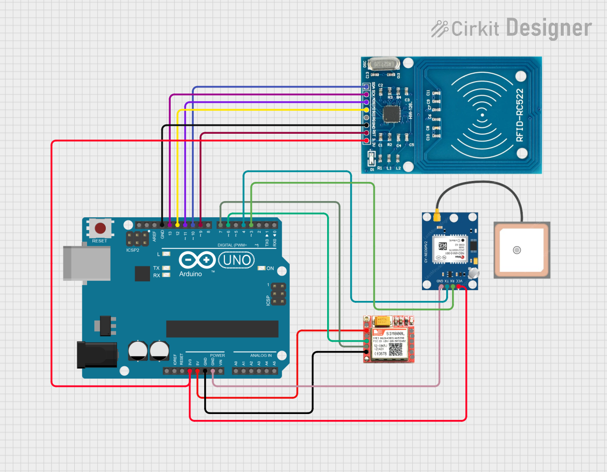
Circuit Documentation
Summary
This circuit integrates an Arduino UNO microcontroller with an RFID-RC522 module, a SIM 800L GSM module, and a GPS NEO 6M module. The system is designed to detect RFID tags, obtain GPS coordinates, and send SMS notifications with the location information.
Component List
Arduino UNO
- Description: A microcontroller board based on the ATmega328P.
- Pins: UNUSED, IOREF, Reset, 3.3V, 5V, GND, Vin, A0, A1, A2, A3, A4, A5, SCL, SDA, AREF, D13, D12, D11, D10, D9, D8, D7, D6, D5, D4, D3, D2, D1, D0
RFID-RC522
- Description: A low-cost RFID reader module.
- Pins: VCC (3.3V), RST, GND, IRQ, MISO, MOSI, SCK, SDA
SIM 800L
- Description: A GSM module for sending and receiving SMS and making calls.
- Pins: NFT, RING, VCC, DTR, RST, MIC +, RXD, MIC-, TXD, SPK+, GND, SPK-
GPS NEO 6M
- Description: A GPS module for obtaining location data.
- Pins: VCC, RX, TX, GND
Wiring Details
Arduino UNO
- 3.3V: Connected to VCC (3.3V) of RFID-RC522 and VCC of GPS NEO 6M
- 5V: Connected to VCC of SIM 800L
- GND: Connected to GND of RFID-RC522, SIM 800L, and GPS NEO 6M
- D13: Connected to SCK of RFID-RC522
- D12: Connected to MISO of RFID-RC522
- D11: Connected to MOSI of RFID-RC522
- D10: Connected to SDA of RFID-RC522
- D9: Connected to RST of RFID-RC522
- D7: Connected to TXD of SIM 800L
- D6: Connected to RXD of SIM 800L
- D4: Connected to TX of GPS NEO 6M
- D3: Connected to RX of GPS NEO 6M
RFID-RC522
- VCC (3.3V): Connected to 3.3V of Arduino UNO
- RST: Connected to D9 of Arduino UNO
- GND: Connected to GND of Arduino UNO
- SCK: Connected to D13 of Arduino UNO
- MISO: Connected to D12 of Arduino UNO
- MOSI: Connected to D11 of Arduino UNO
- SDA: Connected to D10 of Arduino UNO
SIM 800L
- VCC: Connected to 5V of Arduino UNO
- GND: Connected to GND of Arduino UNO
- TXD: Connected to D7 of Arduino UNO
- RXD: Connected to D6 of Arduino UNO
GPS NEO 6M
- VCC: Connected to 3.3V of Arduino UNO
- GND: Connected to GND of Arduino UNO
- TX: Connected to D4 of Arduino UNO
- RX: Connected to D3 of Arduino UNO
Code Documentation
Arduino Code
#include <SPI.h>
#include <MFRC522.h>
#include <SoftwareSerial.h>
#include <TinyGPS++.h>

// RFID Configuration
#define SS_PIN 10
#define RST_PIN 9
MFRC522 rfid(SS_PIN, RST_PIN);

// GSM Configuration
SoftwareSerial gsmSerial(7, 8); // RX, TX for GSM Module
String parentPhone = "+1234567890"; // Parent phone number (replace with actual phone number)

// GPS Configuration
SoftwareSerial gpsSerial(3, 4); // RX, TX for GPS Module
TinyGPSPlus gps; // Create an object of TinyGPS++

String validRFID = "YOUR_RFID_UID";  // Replace with the RFID UID of the student

// LEDs and Buzzer (optional)
int greenLED = 6;
int redLED = 5;
int buzzer = 4;

void setup() {
  // Initialize RFID
  SPI.begin();
  rfid.PCD_Init();
  Serial.begin(9600);
  gsmSerial.begin(9600);
  gpsSerial.begin(9600); // Start GPS serial communication

  // Initialize LEDs and Buzzer
  pinMode(greenLED, OUTPUT);
  pinMode(redLED, OUTPUT);
  pinMode(buzzer, OUTPUT);
}

void loop() {
  if (rfid.PICC_IsNewCardPresent()) {
    if (rfid.PICC_ReadCardSerial()) {
      String rfidUID = "";
      for (byte i = 0; i < rfid.uid.size; i++) {
        rfidUID += String(rfid.uid.uidByte[i], HEX);
      }

      // If the RFID UID matches the student's card, send the SMS
      if (rfidUID == validRFID) {
        digitalWrite(greenLED, HIGH);  // Green LED (entry indication)
        digitalWrite(redLED, LOW);     // Turn off Red LED
        digitalWrite(buzzer, HIGH);    // Turn on Buzzer (optional)

        // Get GPS data
        float latitude = 0.0;
        float longitude = 0.0;

        while (gpsSerial.available() > 0) {
          gps.encode(gpsSerial.read());

          if (gps.location.isUpdated()) {
            latitude = gps.location.lat();
            longitude = gps.location.lng();
            break;
          }
        }

        // Create the message with GPS coordinates
        String message = "Entry detected: Child has entered the school.\n";
        message += "Location: Latitude: " + String(latitude, 6) + ", Longitude: " + String(longitude, 6);

        // Send SMS to the parent with location info
        sendSMS(message);

        delay(5000); // Wait for 5 seconds to keep the indicators on
        digitalWrite(buzzer, LOW);  // Turn off the buzzer
      } else {
        digitalWrite(greenLED, LOW);  // Turn off Green LED
        digitalWrite(redLED, HIGH);   // Red LED (exit indication)
      }

      delay(2000); // Delay for 2 seconds before next card scan
    }
  }
}

// Function to send SMS with GPS location
void sendSMS(String message) {
  gsmSerial.println("AT+CMGF=1");  // Set SMS to text mode
  delay(1000);
  gsmSerial.println("AT+CMGS=\"" + parentPhone + "\"");  // Send SMS to parent's phone number
  delay(1000);
  gsmSerial.println(message);  // The message to send
  delay(1000);
  gsmSerial.write(26);  // End of message (Ctrl+Z)
  delay(1000);
}
This code initializes the RFID, GSM, and GPS modules, and continuously checks for new RFID cards. When a valid RFID card is detected, it retrieves the GPS coordinates and sends an SMS to a predefined phone number with the location information.