ESP32-Controlled Relay Module for Smart Switch Applications
Circuit Documentation
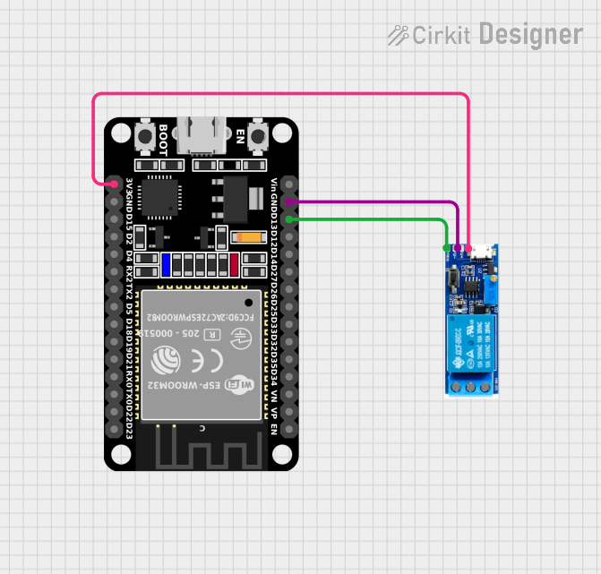
Summary of the Circuit
This circuit consists of an ESP32 microcontroller and a relay module. The ESP32 is a versatile microcontroller with Wi-Fi and Bluetooth capabilities, which can be used for a variety of IoT applications. The relay module allows the ESP32 to control higher power devices, acting as an electrically operated switch. The ESP32 controls the relay by sending a signal to the relay's trigger pin. The circuit is powered by the ESP32's 3.3V output, and the ground is shared between the two components.
Component List
ESP32 (30 pin)
- Description: A 30-pin microcontroller with Wi-Fi and Bluetooth capabilities.
- Pins: EN, VP, VN, D34, D35, D32, D33, D25, D26, D27, D14, D12, D13, GND, Vin, D23, D22, TX0, RX0, D21, D19, D18, D5, TX2, RX2, D4, D2, D15, 3V3
- Purpose: Acts as the central processing unit of the circuit, controlling the relay module and potentially interfacing with other devices or sensors.
Relay module 5v-30v
- Description: A relay module that can switch high-power devices on and off.
- Pins: common contact, normally open, normally closed, trigger, V-, V+
- Purpose: Allows the ESP32 to control devices that require more power than the microcontroller can provide directly.
Wiring Details
ESP32 (30 pin)
- D13: Connected to the trigger pin of the relay module to control the relay.
- GND: Connected to the V- pin of the relay module to provide a common ground reference.
- 3V3: Connected to the V+ pin of the relay module to power the relay.
Relay module 5v-30v
- trigger: Connected to the D13 pin of the ESP32 to receive control signals.
- V-: Connected to the GND pin of the ESP32 to establish a common ground.
- V+: Connected to the 3V3 pin of the ESP32 to receive power.
Documented Code
There is no code provided for the microcontroller at this time. When code is available, it should be documented here with explanations for each function and routine, including how it interacts with the relay module and any other connected devices or sensors.