
Arduino Nano-Based GPS and GSM Tracking System with Load Cell Integration
View and Edit Project In Cirkit Designer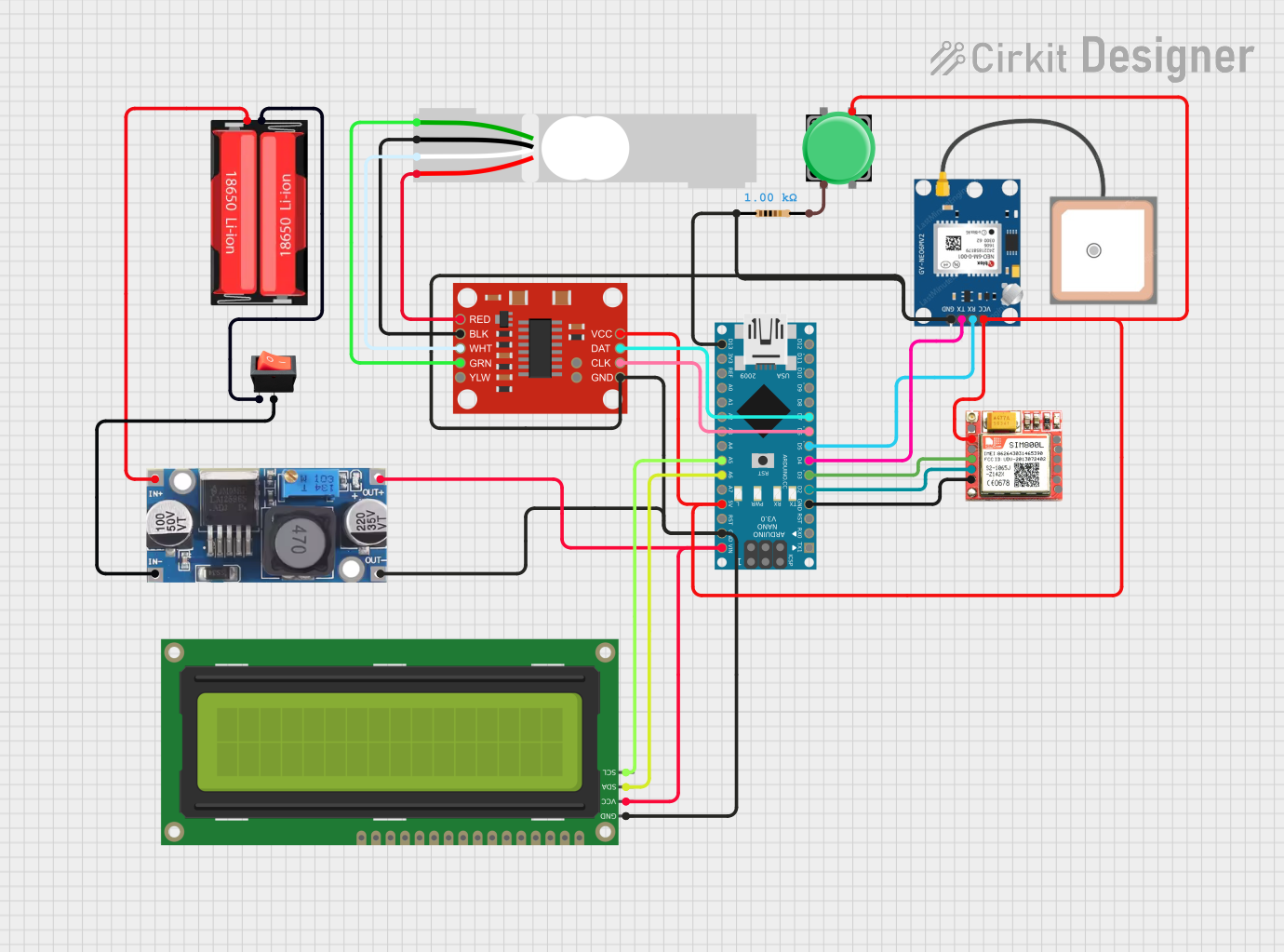
Circuit Documentation
Summary
This circuit integrates various components controlled by an Arduino Nano microcontroller to interface with a GPS module, a GSM module, a load cell with an HX711 amplifier, an I2C LCD display, and a power management system. The circuit is designed to collect location data, communicate over GSM, measure weight with the load cell, and display information on the LCD. Power is supplied by a 18650 Li-Ion battery, regulated by a step-down buck converter, and controlled by a rocker switch.
Component List
Arduino Nano
A compact microcontroller board based on the ATmega328P, featuring digital and analog I/O pins, serial communication capabilities, and power supply options.
GPS NEO 6M
A GPS module capable of providing accurate geographical coordinates, which communicates with the microcontroller via serial interface.
SIM800L
A GSM/GPRS module that allows cellular network connectivity for making calls, sending SMS, and data communication.
Rocker Switch
A simple on/off switch to control the power flow to the circuit.
SparkFun Load Cell Amplifier - HX711
An amplifier specifically designed for load cells to convert analog signals into digital form for the microcontroller to process.
Step-Down Buck Converter
A voltage regulator that steps down the input voltage to a lower, stable output voltage.
18650 Li-Ion Battery
A rechargeable battery providing the power source for the circuit.
Load Cell - Red/White/Black/Green
A transducer that converts force into an electrical signal, used in conjunction with the HX711 amplifier.
Pushbutton
A momentary switch that can be used to trigger actions in the circuit.
Resistor (1k Ohms)
A passive component used to limit current or divide voltages in the circuit.
16x2 I2C LCD
A liquid crystal display that can show 16 characters per line for 2 lines, interfaced via the I2C protocol.
Wiring Details
Arduino Nano
D2connected to SIM800L TXDD3connected to SIM800L RXDD4connected to GPS NEO 6M TXD5connected to GPS NEO 6M RXD6connected to HX711 CLKD7connected to HX711 DATA6connected to 16x2 I2C LCD SDAA5connected to 16x2 I2C LCD SCLVINconnected to Step-Down Buck Converter OUT +GNDconnected to common ground net5Vconnected to common VCC net
GPS NEO 6M
TXconnected to Arduino Nano D4RXconnected to Arduino Nano D5VCCconnected to common VCC netGNDconnected to common ground net
SIM800L
TXDconnected to Arduino Nano D2RXDconnected to Arduino Nano D3VCCconnected to common VCC netGNDconnected to common ground net
Rocker Switch
inputconnected to 18650 Li-Ion Battery Negativeoutputconnected to Step-Down Buck Converter IN - GND
SparkFun Load Cell Amplifier - HX711
CLKconnected to Arduino Nano D6DATconnected to Arduino Nano D7VCCconnected to common VCC netGNDconnected to common ground netREDconnected to Load Cell E+WHTconnected to Load Cell A-BLKconnected to Load Cell E-GRNconnected to Load Cell A+
Step-Down Buck Converter
IN +connected to 18650 Li-Ion Battery PositiveIN - GNDconnected to Rocker Switch outputOUT +connected to common VCC netOUT - GNDconnected to common ground net
18650 Li-Ion Battery
Positiveconnected to Step-Down Buck Converter IN +Negativeconnected to Rocker Switch input
Load Cell - Red/White/Black/Green
E+connected to HX711 REDA-connected to HX711 WHTE-connected to HX711 BLKA+connected to HX711 GRN
Pushbutton
Pin 2connected to Resistor pin2
Resistor (1k Ohms)
pin1connected to common ground netpin2connected to Pushbutton Pin 2
16x2 I2C LCD
VCCconnected to Step-Down Buck Converter OUT +GNDconnected to common ground netSDAconnected to Arduino Nano A6SCLconnected to Arduino Nano A5
Documented Code
Arduino Nano Code (sketch.ino)
void setup() {
  // put your setup code here, to run once:

}

void loop() {
  // put your main code here, to run repeatedly:

}
Note: The provided code is a template and does not include specific functionality. It needs to be populated with the logic to interact with the connected components based on the requirements of the circuit's application.