
Circuit Documentation
Summary of the Circuit
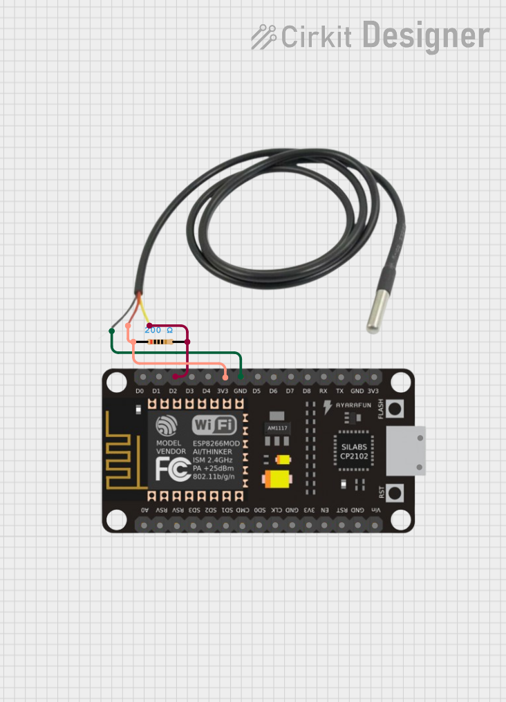
This circuit is designed to interface a temperature sensor with an ESP-8266 microcontroller. The temperature sensor's data line is connected to the microcontroller through a pull-up resistor, which is a common configuration for digital temperature sensors that use a one-wire interface. The sensor is powered by the 3.3V supply from the microcontroller, and its ground is connected to the microcontroller's ground. The ESP-8266 microcontroller is programmed to control an LED connected to one of its digital I/O pins, toggling the LED on and off with a one-second interval.
Component List
Resistor
- Description: A passive two-terminal electrical component that implements electrical resistance as a circuit element.
- Purpose: Used as a pull-up resistor for the temperature sensor's data line.
- Properties: 200 Ohms resistance.
Temperature Sensor
- Description: A sensor that measures temperature.
- Purpose: To provide temperature readings to the microcontroller.
- Properties: Not specified.
ESP-8266 Controller
- Description: A microcontroller with Wi-Fi capabilities.
- Purpose: Acts as the central processing unit of the circuit, reads temperature data, and controls an LED.
- Properties: Not specified.
Wiring Details
Resistor
- Pin1: Connected to the 3.3V supply from the ESP-8266 Controller.
- Pin2: Connected to the data line (Temp DQ Data Yellow) of the Temperature Sensor and the D2 pin of the ESP-8266 Controller.
Temperature Sensor
- Temp GND Black: Connected to the GND pin of the ESP-8266 Controller.
- Temp VDD Red: Connected to Pin1 of the Resistor (which is connected to the 3.3V supply of the ESP-8266 Controller).
- Temp DQ Data Yellow: Connected to Pin2 of the Resistor and the D2 pin of the ESP-8266 Controller.
ESP-8266 Controller
- 3V3: Provides power to the Resistor and the Temperature Sensor.
- GND: Common ground for the Temperature Sensor.
- D2: Receives the temperature data from the Temperature Sensor.
- D0: Configured as an output to control an LED.
Documented Code
The following code is written for the ESP-8266 microcontroller to control an LED connected to the D0 pin. The LED is turned on and off every second.
int led = D0;

void setup() {
  pinMode(led, OUTPUT);
  Serial.begin(115200);
}

void loop() {
  digitalWrite(led, HIGH);
  delay(1000); // Wait for 1000 millisecond(s)
  digitalWrite(led, LOW);
  delay(1000); // Wait for 1000 millisecond(s)
}
- File Name: sketch.ino
- Description: This sketch initializes the D0 pin as an output to control an LED. It also sets up the serial communication at a baud rate of 115200. In the loop function, the LED is turned on for one second and then turned off for one second, repeatedly.
(Note: The actual connection of the LED to the D0 pin is not described in the provided net list and should be added to the circuit for the code to function as intended.)