Arduino-Controlled Motor Driver with LCD Interface
Circuit Documentation
Summary
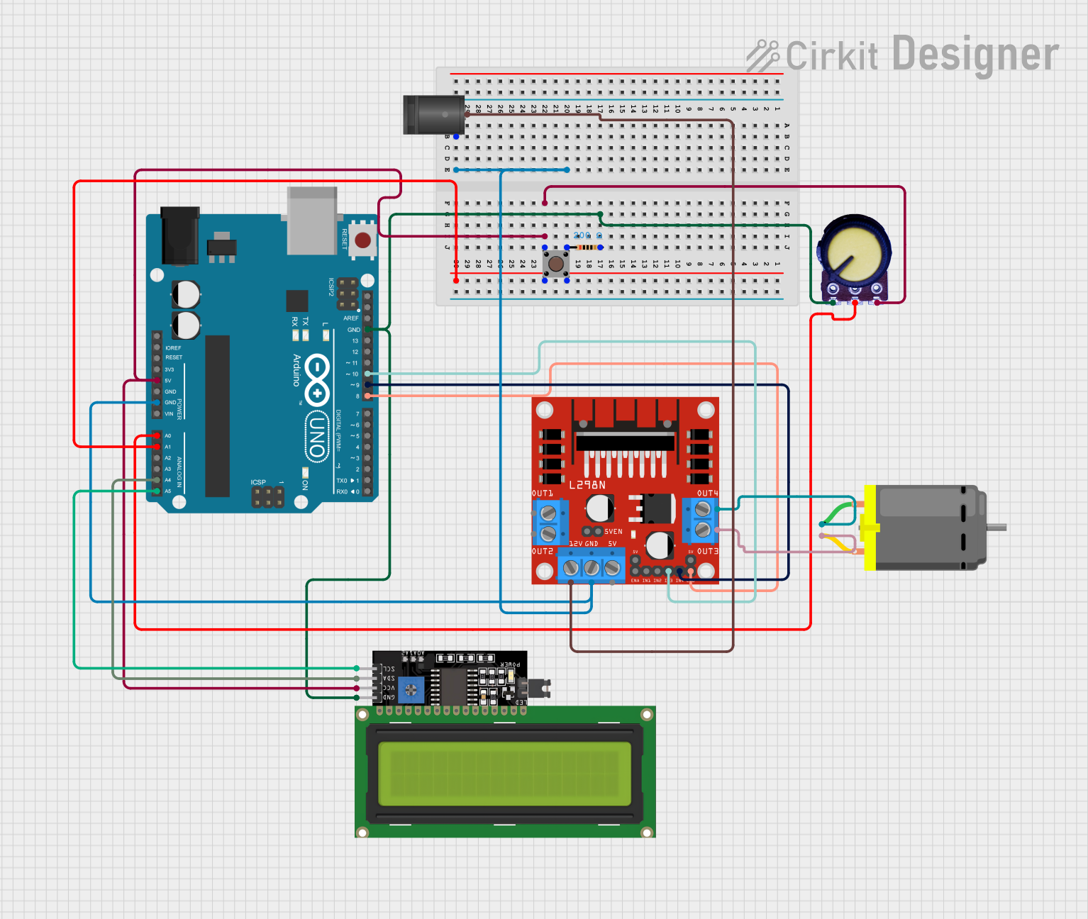
This circuit is designed to control a DC motor using an Arduino UNO microcontroller and an L298N DC motor driver. It includes a pushbutton for input, a potentiometer for adjusting parameters, and an LCD display for user feedback. The circuit is powered by a 2.1mm DC Barrel Jack, which supplies power to the motor driver and the Arduino UNO. The Arduino UNO manages the motor driver's inputs and communicates with the LCD display via I2C.
Component List
Arduino UNO
- Microcontroller board based on the ATmega328P
- It has 14 digital input/output pins, 6 analog inputs, a 16 MHz quartz crystal, a USB connection, a power jack, an ICSP header, and a reset button.
Pushbutton
- A simple switch mechanism for controlling some aspect of a machine or a process. Buttons are typically made out of hard material, usually plastic or metal.
Resistor (200 Ohms)
- A passive two-terminal electrical component that implements electrical resistance as a circuit element.
L298N DC Motor Driver
- An integrated monolithic circuit in a 15-lead Multiwatt and PowerSO20 packages. It is a high voltage, high current dual full-bridge driver designed to accept standard TTL logic levels.
Potentiometer
- A three-terminal resistor with a sliding or rotating contact that forms an adjustable voltage divider.
LCD Display 16x4 I2C
- A liquid crystal display that can show up to 16 characters per line and has 4 lines. It uses the I2C communication protocol.
DC Motor
- A machine that converts electrical energy into mechanical energy.
2.1mm DC Barrel Jack
- A common power connector for electronic devices. It consists of a cylindrical connector with an associated mating plug.
Wiring Details
Arduino UNO
- GND connected to common ground.
- 5V supplies power to the Potentiometer, LCD Display, and Pushbutton.
- A0 connected to the Potentiometer output.
- A1 connected to the Pushbutton.
- A4 (SDA) connected to the LCD Display SDA pin.
- A5 (SCL) connected to the LCD Display SCL pin.
- D8 connected to the L298N DC motor driver ENB.
- D9 connected to the L298N DC motor driver IN4.
- D10 connected to the L298N DC motor driver IN3.
Pushbutton
- One side connected to the Arduino UNO A1 pin and the other side to the 200 Ohms Resistor.
Resistor (200 Ohms)
- Connected between the Pushbutton and ground.
L298N DC Motor Driver
- GND connected to common ground.
- 12V connected to the 2.1mm DC Barrel Jack center pin.
- IN3 connected to the Arduino UNO D10 pin.
- IN4 connected to the Arduino UNO D9 pin.
- ENB connected to the Arduino UNO D8 pin.
- OUT3 and OUT4 connected to the DC Motor.
Potentiometer
- GND connected to common ground.
- Output connected to the Arduino UNO A0 pin.
- VCC connected to the Arduino UNO 5V pin.
LCD Display 16x4 I2C
- GND connected to common ground.
- VCC connected to the Arduino UNO 5V pin.
- SDA connected to the Arduino UNO A4 pin.
- SCL connected to the Arduino UNO A5 pin.
DC Motor
- Connected to the L298N DC motor driver OUT3 and OUT4.
2.1mm DC Barrel Jack
- Sleeve connected to common ground.
- Center connected to the L298N DC motor driver 12V pin.
Documented Code
sketch.ino
void setup() {
  // put your setup code here, to run once:

}

void loop() {
  // put your main code here, to run repeatedly:

}
documentation.txt
(No additional documentation provided for the code)
This concludes the documentation for the given circuit. The circuit is designed to control a DC motor with the capability of adjusting parameters through a potentiometer and receiving user input via a pushbutton. The LCD display provides a user interface for feedback. The Arduino UNO serves as the central controller, interfacing with the motor driver and the display.