
Arduino UNO and HC-05 Bluetooth Controlled LED Array with I2C LCD Display
View and Edit Project In Cirkit Designer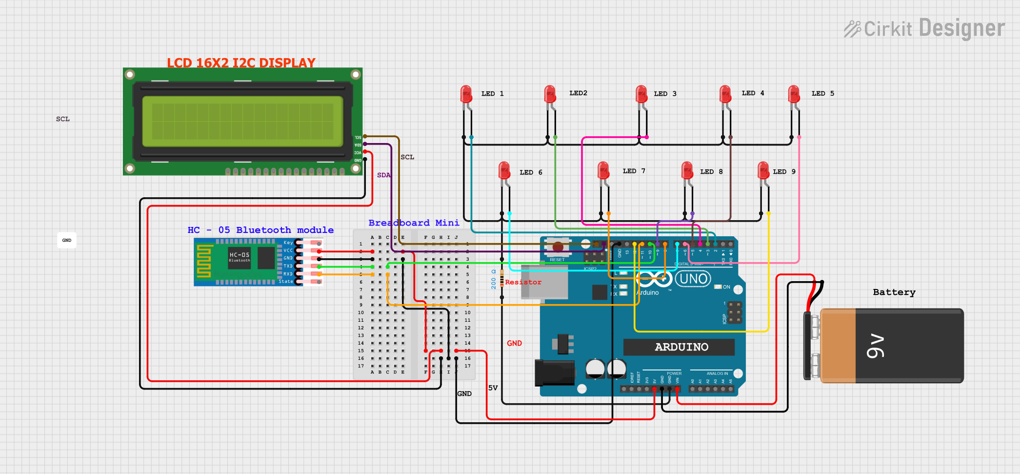
Circuit Documentation
Summary
This circuit is designed to interface an Arduino UNO with an HC-05 Bluetooth module, an I2C LCD 16x2 screen, and multiple red two-pin LEDs. The Arduino UNO serves as the central microcontroller unit, controlling the LEDs and communicating with the HC-05 Bluetooth module and the LCD screen. The HC-05 module enables Bluetooth connectivity, while the LCD screen displays information. The LEDs are used as indicators and are connected to various digital pins on the Arduino UNO. A 9V battery powers the circuit, and a resistor is used to limit current to the LEDs.
Component List
- Arduino UNO: A microcontroller board based on the ATmega328P, equipped with digital and analog I/O pins.
- HC-05 Bluetooth Module: A Bluetooth module for wireless communication.
- I2C LCD 16x2 Screen: A liquid crystal display with 16 characters per line and 2 lines, using the I2C communication protocol.
- LED: Two Pin (red): A red light-emitting diode with an anode and cathode pin.
- Resistor: A passive two-terminal electrical component that implements electrical resistance as a circuit element.
- 9V Battery: A standard 9V battery used to power the circuit.
Wiring Details
Arduino UNO
- 5V: Connected to the VCC of the HC-05 Bluetooth module and VCC (5V) of the I2C LCD 16x2 screen.
- GND: Common ground for the HC-05 Bluetooth module, I2C LCD 16x2 screen, and one terminal of the resistor.
- Vin: Connected to the positive terminal of the 9V battery.
- Digital Pins (D2-D12): Connected to the anodes of the red LEDs.
- SCL: Connected to the SCL pin of the I2C LCD 16x2 screen.
- SDA: Connected to the SDA pin of the I2C LCD 16x2 screen.
HC-05 Bluetooth Module
- VCC: Powered by the 5V output from the Arduino UNO.
- GND: Connected to the common ground.
- TXD: Connected to the D10 pin on the Arduino UNO.
- RXD: Connected to the D11 pin on the Arduino UNO.
I2C LCD 16x2 Screen
- VCC (5V): Powered by the 5V output from the Arduino UNO.
- GND: Connected to the common ground.
- SCL: Connected to the SCL pin on the Arduino UNO.
- SDA: Connected to the SDA pin on the Arduino UNO.
LEDs: Two Pin (red)
- Anode: Each LED anode is connected to a unique digital pin on the Arduino UNO (D2-D12).
- Cathode: All LED cathodes are connected together and then to one terminal of the resistor.
Resistor
- Pin1: Connected to the common ground.
- Pin2: Connected to the cathodes of all the red LEDs.
9V Battery
- +: Connected to the Vin pin on the Arduino UNO.
- -: Connected to the common ground.
Documented Code
Arduino UNO
File: sketch.ino
void setup() {
  // put your setup code here, to run once:

}

void loop() {
  // put your main code here, to run repeatedly:

}
File: documentation.txt
(No additional documentation provided)
This concludes the documentation for the given circuit. The code provided is a template and does not include any functionality. To complete the circuit's operation, the user must add code to control the LEDs, read data from the HC-05 Bluetooth module, and display information on the I2C LCD screen.