
Arduino UNO-Based Fire and Smoke Detection System with LCD Display and Motor Control
View and Edit Project In Cirkit Designer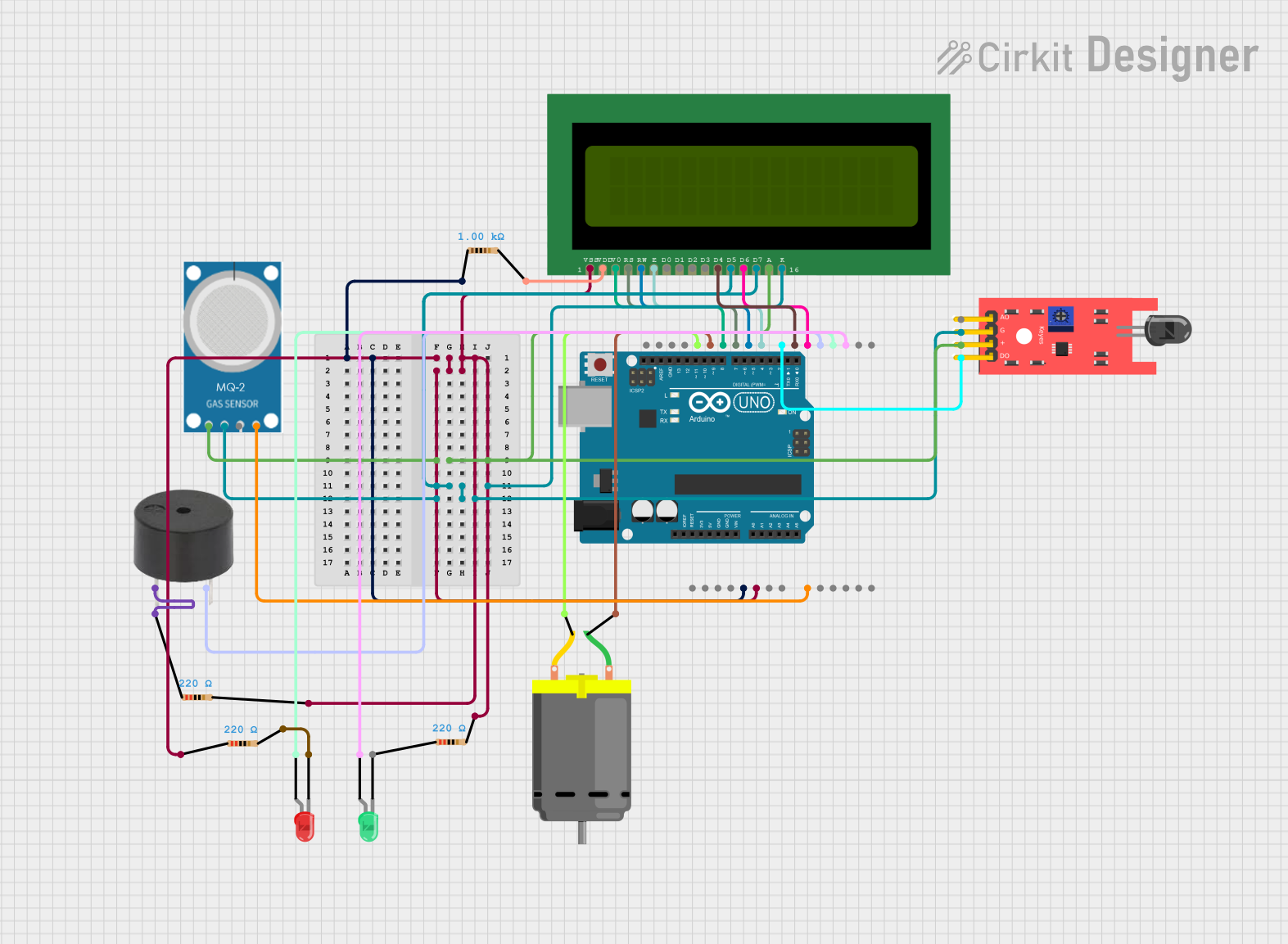
Circuit Documentation
Summary
This circuit is designed to detect smoke and fire using an MQ-2 gas sensor and a KY-026 flame sensor. It uses an Arduino UNO to process the sensor data and control various outputs, including an LCD display, LEDs, a buzzer, and a DC motor. The LCD displays messages based on the sensor readings, while the LEDs and buzzer provide visual and auditory alerts. The DC motor is used to simulate an action, such as activating a fan or other device, in response to the detected conditions.
Component List
Arduino UNO
- Description: A microcontroller board based on the ATmega328P.
- Pins: UNUSED, IOREF, Reset, 3.3V, 5V, GND, Vin, A0, A1, A2, A3, A4, A5, SCL, SDA, AREF, D13, D12, D11, D10, D9, D8, D7, D6, D5, D4, D3, D2, D1, D0
LCD 16x2 (Wokwi Compatible)
- Description: A 16x2 character LCD display.
- Pins: VSS, VDD, V0, RS, RW, E, D0, D1, D2, D3, D4, D5, D6, D7, A, K
DC Motor
- Description: A simple DC motor.
- Pins: pin 1, pin 2
MQ-2
- Description: A gas sensor for detecting smoke and combustible gases.
- Pins: GND, VCC, ANALOG, Digital
KY-026 Flame Sensor
- Description: A sensor for detecting flame.
- Pins: A0, GND, VCC, D0
Resistor (1000 Ohms)
- Description: A resistor with a resistance of 1000 Ohms.
- Pins: pin1, pin2
Resistor (220 Ohms)
- Description: A resistor with a resistance of 220 Ohms.
- Pins: pin1, pin2
LED: Two Pin (green)
- Description: A green LED.
- Pins: cathode, anode
LED: Two Pin (red)
- Description: A red LED.
- Pins: cathode, anode
Buzzer
- Description: A simple buzzer.
- Pins: PIN, GND
Wiring Details
Arduino UNO
- 5V connected to pin1 of Resistor (1000 Ohms)
- GND connected to pin2 of Resistor (220 Ohms), pin2 of Resistor (220 Ohms), pin2 of Resistor (220 Ohms), and VSS of LCD 16x2 (Wokwi Compatible)
- A0 connected to Digital of MQ-2
- D13 connected to pin 2 of DC Motor
- D12 connected to pin 1 of DC Motor
- D11 connected to V0 of LCD 16x2 (Wokwi Compatible)
- D10 connected to RS of LCD 16x2 (Wokwi Compatible)
- D9 connected to RW of LCD 16x2 (Wokwi Compatible)
- D8 connected to E of LCD 16x2 (Wokwi Compatible)
- D7 connected to D0 of KY-026 Flame Sensor
- D6 connected to D4 of LCD 16x2 (Wokwi Compatible)
- D5 connected to D6 of LCD 16x2 (Wokwi Compatible)
- D4 connected to GND of Buzzer
- D3 connected to anode of LED: Two Pin (red)
- D2 connected to anode of LED: Two Pin (green)
LCD 16x2 (Wokwi Compatible)
- VSS connected to GND of Arduino UNO
- VDD connected to pin2 of Resistor (1000 Ohms)
- V0 connected to D11 of Arduino UNO
- RS connected to D10 of Arduino UNO
- RW connected to D9 of Arduino UNO
- E connected to D8 of Arduino UNO
- D4 connected to D6 of Arduino UNO
- D5 connected to D5 of Arduino UNO
- D6 connected to D5 of Arduino UNO
- D7 connected to D5 of LCD 16x2 (Wokwi Compatible)
- A connected to GND of MQ-2
- K connected to D7 of LCD 16x2 (Wokwi Compatible)
DC Motor
- pin 1 connected to D12 of Arduino UNO
- pin 2 connected to D13 of Arduino UNO
MQ-2
- GND connected to A of LCD 16x2 (Wokwi Compatible)
- VCC connected to D5 of LCD 16x2 (Wokwi Compatible)
- Digital connected to A0 of Arduino UNO
KY-026 Flame Sensor
- A0 not connected
- GND connected to D5 of LCD 16x2 (Wokwi Compatible)
- VCC connected to A of LCD 16x2 (Wokwi Compatible)
- D0 connected to D7 of Arduino UNO
Resistor (1000 Ohms)
- pin1 connected to 5V of Arduino UNO
- pin2 connected to VDD of LCD 16x2 (Wokwi Compatible)
Resistor (220 Ohms)
- pin1 connected to GND of Arduino UNO
- pin2 connected to VSS of LCD 16x2 (Wokwi Compatible)
LED: Two Pin (green)
- cathode not connected
- anode connected to D2 of Arduino UNO
LED: Two Pin (red)
- cathode connected to pin2 of Resistor (220 Ohms)
- anode connected to D3 of Arduino UNO
Buzzer
- PIN connected to pin1 of Resistor (220 Ohms)
- GND connected to D4 of Arduino UNO
Code Documentation
#include <LiquidCrystal.h>
LiquidCrystal lcd(5,6,8,9,10,11);

int redled = 2;
int greenled = 3;
int buzzer = 4;
int sensor = A0;
int sensorThresh = 400;
int terminaliMotorrit1=12;
int terminaliMotorrit2=13;
int flameSensor=7;

void setup()
{
  pinMode(redled, OUTPUT);
  pinMode(flameSensor, INPUT);
  pinMode(greenled, OUTPUT);
  pinMode(buzzer, OUTPUT);
  pinMode(sensor, INPUT);
  pinMode(terminaliMotorrit1, OUTPUT);
  pinMode(terminaliMotorrit2, OUTPUT);
  Serial.begin(9600);
  lcd.begin(16,2);
}

void loop()
{
  int fire = digitalRead(flameSensor);
  int analogValue = analogRead(sensor);
  Serial.print(analogValue);

  if(analogValue > sensorThresh || fire == HIGH)
  {
    digitalWrite(redled, HIGH);
    digitalWrite(greenled, LOW);
    tone(buzzer, 1000, 10000);
    lcd.clear();
    lcd.setCursor(0, 1);
    lcd.print("TURRU SHUM ZJARR");
    delay(1000);
    lcd.clear();
    lcd.setCursor(0, 1);
    lcd.print("LLUUUK LLUUUK");
    digitalWrite(terminaliMotorrit1, HIGH);
    digitalWrite(terminaliMotorrit2, LOW);
    delay(1000);
  }
  else
  {
    digitalWrite(greenled, HIGH);
    digitalWrite(redled, LOW);
    noTone(buzzer);
    lcd.clear();
    lcd.setCursor(0, 0);
    lcd.print("NO SMOKE &");
    delay(1000);
    lcd.clear();
    lcd.setCursor(0, 1);
    lcd.print("NO FIRE DETECTED");
    delay(1000);
    digitalWrite(terminaliMotorrit1, LOW);
    digitalWrite(terminaliMotorrit2, LOW);
  }
}
This code initializes the LCD, LEDs, buzzer,