
Arduino-Controlled Bluetooth Robotic Vehicle with Ultrasonic Obstacle Avoidance
View and Edit Project In Cirkit Designer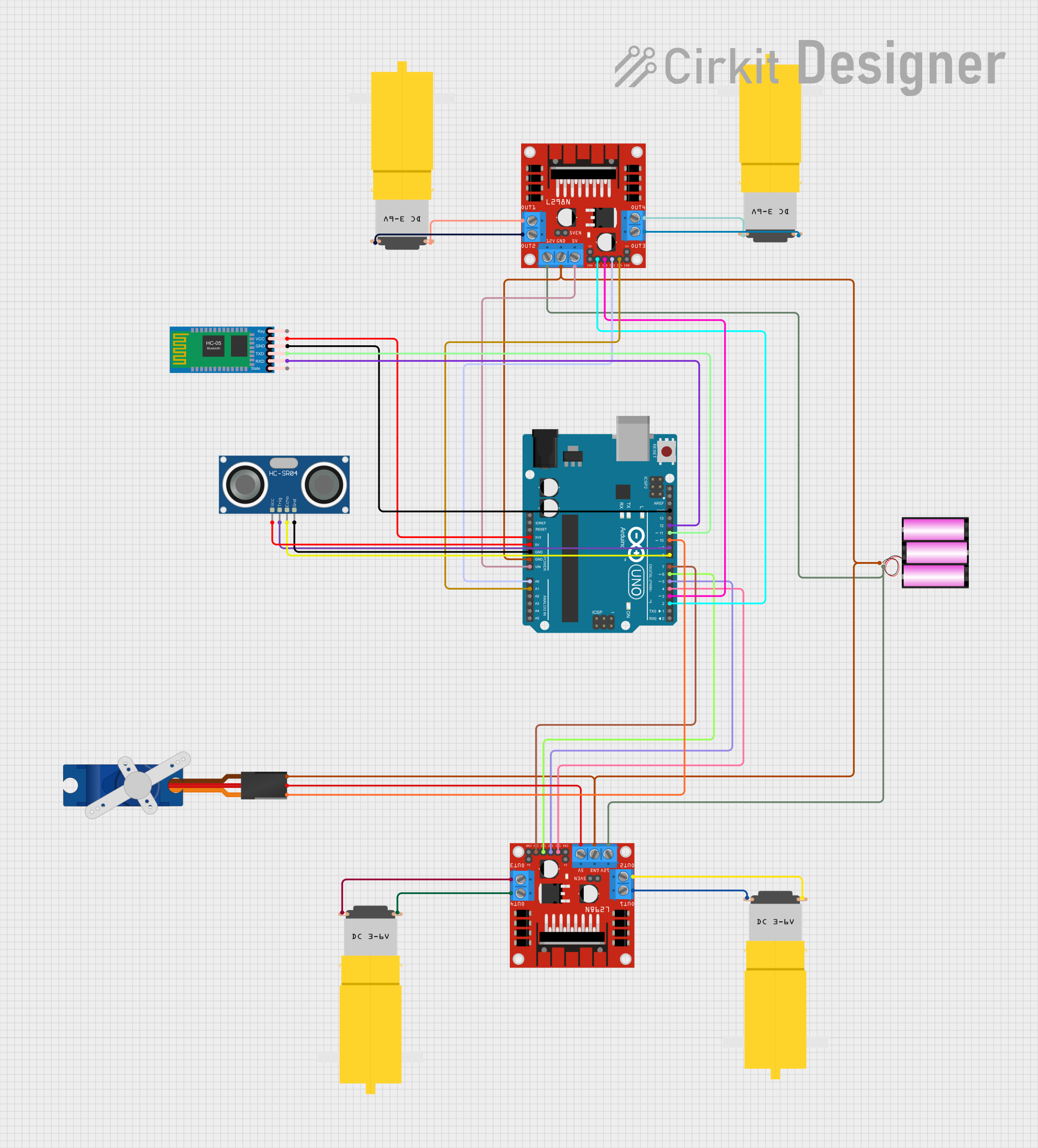
Circuit Documentation
Summary
This circuit is designed to control a robotic vehicle with four hobby motors, a servo, an ultrasonic sensor, and Bluetooth communication capabilities. The core of the circuit is an Arduino UNO microcontroller, which interfaces with an HC-05 Bluetooth module for remote commands, an HC-SR04 ultrasonic sensor for distance measurement, and two L298N DC motor drivers to control the motors. A 12V battery provides power to the motor drivers and the servo, while the Arduino regulates power to the Bluetooth module and the ultrasonic sensor. The servo is controlled directly by the Arduino.
Component List
Motors
- Motor Amarillo Motorreductor Hobby: A DC gear motor used for driving the robotic vehicle.
Motor Drivers
- L298N DC Motor Driver: A dual H-bridge motor driver that allows for speed and direction control of two DC motors.
Microcontroller
- Arduino UNO: The main controller used to interface with sensors, motor drivers, and the Bluetooth module.
Bluetooth Module
- HC-05 Bluetooth Module: A wireless communication module that enables remote control via Bluetooth.
Ultrasonic Sensor
- HC-SR04 Ultrasonic Sensor: A sensor that measures distance by emitting ultrasonic waves and timing their return after bouncing off objects.
Servo
- Tower Pro SG90 Servo: A small and lightweight servo motor for precision control.
Power Supply
- Battery 12V: Provides power to the motor drivers and the servo motor.
Wiring Details
Motor Amarillo Motorreductor Hobby
- VCC: Connected to the output pins (OUT1/OUT2 or OUT3/OUT4) of the L298N motor drivers.
- GND: Connected to the output pins (OUT1/OUT2 or OUT3/OUT4) of the L298N motor drivers.
L298N DC Motor Driver
- OUT1, OUT2, OUT3, OUT4: Connected to the motors.
- 12V: Connected to the 12V battery.
- GND: Common ground with the Arduino, servo, and battery.
- 5V: Provides power to the servo motor.
- ENA, ENB: Enable pins for the motor outputs, not explicitly controlled in the provided code.
- IN1, IN2, IN3, IN4: Control pins connected to the Arduino digital pins for motor direction control.
HC-05 Bluetooth Module
- VCC: Connected to the 3.3V output of the Arduino.
- GND: Common ground with the Arduino.
- TXD: Connected to the D11 pin of the Arduino.
- RXD: Connected to the D12 pin of the Arduino.
HC-SR04 Ultrasonic Sensor
- VCC: Connected to the 5V output of the Arduino.
- GND: Common ground with the Arduino.
- TRIG: Connected to the D9 pin of the Arduino.
- ECHO: Connected to the D8 pin of the Arduino.
Tower Pro SG90 Servo
- Signal: Connected to the D10 pin of the Arduino.
- +5V: Powered by the 5V output from the L298N motor driver.
- GND: Common ground with the battery and Arduino.
Arduino UNO
- 3.3V: Powers the HC-05 Bluetooth module.
- 5V: Powers the HC-SR04 ultrasonic sensor.
- GND: Common ground for all components.
- Vin: Receives power from the 5V output of the L298N motor driver.
- Digital Pins (D2-D12): Control various components such as the motors, servo, and Bluetooth module.
- Analog Pins (A0, A1): Used as digital outputs to control additional motor driver inputs.
Documented Code
#include <Servo.h>
#include <SoftwareSerial.h>

Servo Myservo;

// First L298N Motor Driver
#define MLa 4               // left motor 1st pin
#define MLb 5               // left motor 2nd pin
#define MRa 6               // right motor 1st pin
#define MRb 7               // right motor 2nd pin

// Second L298N Motor Driver (Updated pins)
#define ML2a 2              // second left motor 1st pin
#define ML2b 3              // second left motor 2nd pin
#define MR2a A0             // second right motor 1st pin (using analog pin as digital)
#define MR2b A1             // second right motor 2nd pin (using analog pin as digital)

// Ultrasonic Sensor
#define trigPin 9
#define echoPin 8

// Bluetooth and Buzzer
#define buzzerPin 10
#define BT_RX 11            // RX pin of Bluetooth
#define BT_TX 12            // TX pin of Bluetooth (set back to pin 12)

SoftwareSerial BTSerial(BT_RX, BT_TX);

long duration, distance;
bool automaticMode = true;

void setup() {
  Serial.begin(9600);
  BTSerial.begin(9600);      // Begin Bluetooth communication

  // Set Motor Pins As OUTPUT for both L298Ns
  pinMode(MLa, OUTPUT);
  pinMode(MLb, OUTPUT);
  pinMode(MRa, OUTPUT);
  pinMode(MRb, OUTPUT);

  pinMode(ML2a, OUTPUT);
  pinMode(ML2b, OUTPUT);
  pinMode(MR2a, OUTPUT);
  pinMode(MR2b, OUTPUT);

  // Set ultrasonic sensor and buzzer
  pinMode(trigPin, OUTPUT);
  pinMode(echoPin, INPUT);
  pinMode(buzzerPin, OUTPUT);

  Myservo.attach(10);        // Attach Servo to Pin 10
}

void loop() {
  if (BTSerial.available()) {
    char command = BTSerial.read();
    if (command == 'A') {
      automaticMode = true;
      Serial.println("Automatic Mode");
    } else if (command == 'M') {
      automaticMode = false;
      Serial.println("Manual Mode");
    } else if (command == 'H') {
      playHornSound();
    } else if (!automaticMode) {
      // Manual control via Bluetooth
      manualControl(command);
    }
  }

  if (automaticMode) {
    obstacleAvoidance();
  }
}

void obstacleAvoidance() {
  digitalWrite(trigPin, LOW);
  delayMicroseconds(2);
  digitalWrite(trigPin, HIGH);
  delayMicroseconds(10);
  digitalWrite(trigPin, LOW);

  duration = pulseIn(echoPin, HIGH);
  distance = duration / 58.2;
  Serial.println(distance);
  delay(10);

  if (distance > 15) {  // No obstacle
    Myservo.write(90);
    moveForward();
  } else if (distance < 10 && distance > 0) {  // Obstacle detected
    stopMoving();
    delay(100);

    Myservo.write(0);
    delay(500);
    Myservo.write(180);
    delay(500);
    Myservo.write(90);
    delay(500);

    moveBackward();
    delay(500);
    stopMoving();
    delay(100);
    turnLeft();
    delay(500);

    // Optional: Play a sound when obstacle is detected
    playObstacleSound();
  }
}

// Manual control function
void manualControl(char command) {
  switch (command) {
    case 'F':
      moveForward();
      break;
    case 'B':
      moveBackward();
      break;
    case 'L':
      turnLeft();
      break;
    case 'R':
      turnRight();
      break;
    case 'S':
      stopMoving();
      break;
    default:
      stopMoving();
      break;
  }
}

// Motor control for both L298N motor drivers
void moveForward() {
  // First L298N
  digitalWrite(MRa, HIGH);
  digitalWrite(MRb, LOW);
  digitalWrite(MLa, HIGH);
  digitalWrite(MLb, LOW);

  // Second L298N
  digitalWrite(MR2a, HIGH);
  digitalWrite(MR2b, LOW);
  digitalWrite(ML2a, HIGH);
  digitalWrite(ML2b, LOW);
}

void moveBackward() {
  // First L298N
  digitalWrite(MRa, LOW);
  digitalWrite(MRb, HIGH);
  digitalWrite(MLa, LOW);
  digitalWrite(MLb, HIGH);

  // Second L298N
  digitalWrite(MR2a, LOW);
  digitalWrite(MR2b, HIGH);
  digitalWrite(ML2a, LOW);
  digitalWrite(ML2b, HIGH);
}

void turnLeft() {
  // First L298N
  digitalWrite(MRa, LOW);
  digitalWrite(MRb, HIGH);
  digitalWrite(MLa, HIGH);
  digitalWrite(MLb, LOW);

  // Second L298N
  digitalWrite(MR2a, LOW);
  digitalWrite(MR2b, HIGH);
  digitalWrite(ML2a, HIGH);
  digitalWrite(ML2b, LOW);
}

void turnRight() {
  // First L298N
  digitalWrite(MRa, HIGH);
  digitalWrite(MRb, LOW);
  digitalWrite(MLa, LOW);
  digitalWrite(MLb, HIGH);

  // Second L298N
  digitalWrite(MR2a, HIGH);
  digitalWrite(MR