Cirkit Designer
Your all-in-one circuit design IDE
Home /
Project Documentation
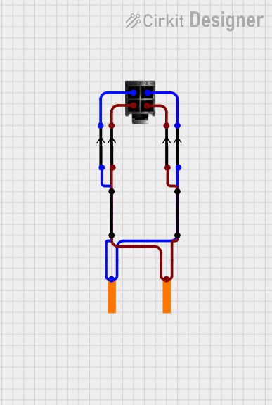
4-Pin Connector Circuit for Edge Detection

Circuit Documentation
Summary
This document provides a detailed overview of the circuit, including a list of components, their descriptions, wiring details, and any embedded code used in the circuit. The circuit consists of various pins, connectors, and points, interconnected to form a functional system.
Component List
4 пин
- Description: A 4-pin connector with red and black pins.
- Pins: красный, черный
pin
- Description: A generic pin.
- Pins: None
край
- Description: A connector with a single pin labeled "край".
- Pins: край
точка
- Description: A point in the circuit.
- Pins: None
Wiring Details
4 пин
красный Pin Connections:
- Connected to pin
- Connected to pin
черный Pin Connections:
- Connected to pin
- Connected to pin
pin
- Pin Connections:
- Connected to 4 пин (красный)
- Connected to 4 пин (красный)
- Connected to 4 пин (черный)
- Connected to 4 пин (черный)
- Connected to pin
- Connected to край (край)
край
- край Pin Connections:
- Connected to pin
- Connected to pin
точка
- Pin Connections:
- Connected to точка
- Connected to точка
Embedded Code
There is no embedded code provided for this circuit.
This document provides a comprehensive overview of the circuit, detailing each component and its connections. If there are any updates or changes to the circuit, please ensure this document is updated accordingly.