Cirkit Designer
Your all-in-one circuit design IDE
Home /
Project Documentation
IoT Biometric and RFID Security System with GSM and Wireless Communication
Circuit Documentation
Summary
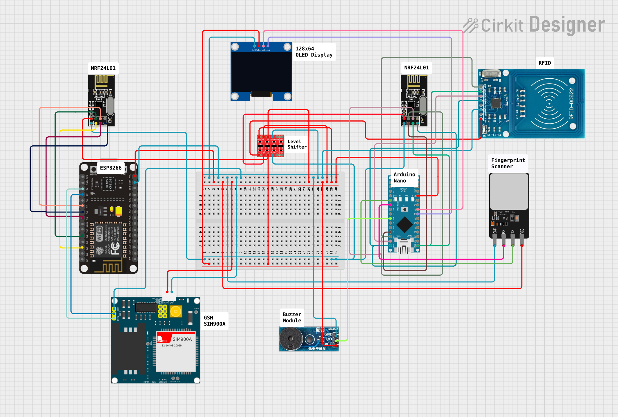
This circuit integrates various components to achieve a multifunctional system. It includes microcontrollers (ESP8266 NodeMCU and Arduino Nano), communication modules (NRF24L01, SIM900A), a bi-directional logic level converter, a fingerprint scanner, a buzzer module, an OLED display, and an RFID-RC522 module. The circuit is designed to handle wireless communication, fingerprint scanning, RFID reading, and user interaction through a display and audio feedback.
Component List
Microcontrollers
- ESP8266 NodeMCU: A Wi-Fi enabled microcontroller with multiple digital and analog pins.
- Arduino Nano: A compact microcontroller with digital and analog I/O pins.
Communication Modules
- NRF24L01: A wireless transceiver module for enabling RF communication.
- SIM900A: A GSM/GPRS module for cellular network communication.
Sensors and Actuators
- Fingerprint Scanner: A biometric sensor for fingerprint detection and verification.
- Buzzer Module: An audio signaling device.
Display
- 128x64 OLED Display (I2C IIC SPI Serial): A small screen for displaying text and graphics.
Other Components
- Bi-Directional Logic Level Converter: A device to safely step down or step up signal voltages between different logic levels.
- RFID-RC522: An RFID reader/writer module.
Wiring Details
ESP8266 NodeMCU
- GND: Connected to the common ground net.
- VIN: Connected to the 5V power net.
- D2: Connected to NRF24L01 CE pin.
- D4: Connected to NRF24L01 CSN pin.
- D5: Connected to NRF24L01 SCK pin.
- D6: Connected to NRF24L01 MISO pin.
- D7: Connected to NRF24L01 MOSI pin.
- RX: Connected to SIM900A RXD pin.
- TX: Connected to SIM900A TXD pin.
Arduino Nano
- 5V: Connected to the 5V power net.
- GND: Connected to the common ground net.
- D2: Connected to Fingerprint Scanner TX pin.
- D3: Connected to Fingerprint Scanner RX pin.
- D6: Connected to Buzzer Module I/O pin.
- D9: Connected to NRF24L01 CE pin.
- D10: Connected to RFID-RC522 SDA and NRF24L01 CSN pins.
- D11/MOSI: Connected to RFID-RC522 MOSI and NRF24L01 MOSI pins.
- D12/MISO: Connected to RFID-RC522 MISO and NRF24L01 MISO pins.
- D13/SCK: Connected to RFID-RC522 SCK and NRF24L01 SCK pins.
- A4: Connected to OLED Display SDA pin.
- A5: Connected to OLED Display SCL pin.
NRF24L01
- GND: Connected to the common ground net.
- VCC (3V): Connected to the 3.3V power net.
- CE, CSN, SCK, MISO, MOSI: Connected to corresponding pins on ESP8266 NodeMCU or Arduino Nano as detailed above.
SIM900A
- GND: Connected to the common ground net.
- 5V: Connected to the 5V power net.
- RXD: Connected to ESP8266 NodeMCU TX pin.
- TXD: Connected to ESP8266 NodeMCU RX pin.
Fingerprint Scanner
- VCC: Connected to the 5V power net.
- GND: Connected to the common ground net.
- TX: Connected to Arduino Nano D2 pin.
- RX: Connected to Arduino Nano D3 pin.
Buzzer Module
- Vcc: Connected to the 5V power net.
- GND: Connected to the common ground net.
- I/O: Connected to Arduino Nano D6 pin.
OLED Display
- VCC: Connected to the 3.3V power net.
- GND: Connected to the common ground net.
- SDA: Connected to Arduino Nano A4 pin.
- SCL: Connected to Arduino Nano A5 pin.
Bi-Directional Logic Level Converter
- GND: Connected to the common ground net.
- LV: Connected to the 3.3V power net.
- HV: Connected to the 5V power net.
- LV1, LV2: Connected to 3.3V power net or NRF24L01 VCC as detailed above.
- HV1, HV2: Connected to 5V power net as detailed above.
RFID-RC522
- VCC (3.3V): Connected to the 3.3V power net.
- GND: Connected to the common ground net.
- SDA, MOSI, MISO, SCK: Connected to corresponding pins on Arduino Nano as detailed above.
Documented Code
Arduino Nano Code (sketch.ino)
void setup() {
  // put your setup code here, to run once:

}

void loop() {
  // put your main code here, to run repeatedly:

}
Note: The provided code for the Arduino Nano is a template with empty setup and loop functions. This code needs to be populated with the logic required to control the connected components based on the desired functionality of the circuit.