ESP8266 NodeMCU Controlled Relay System with Multi-Color LED Indicators and DC Motor
Circuit Documentation
Summary
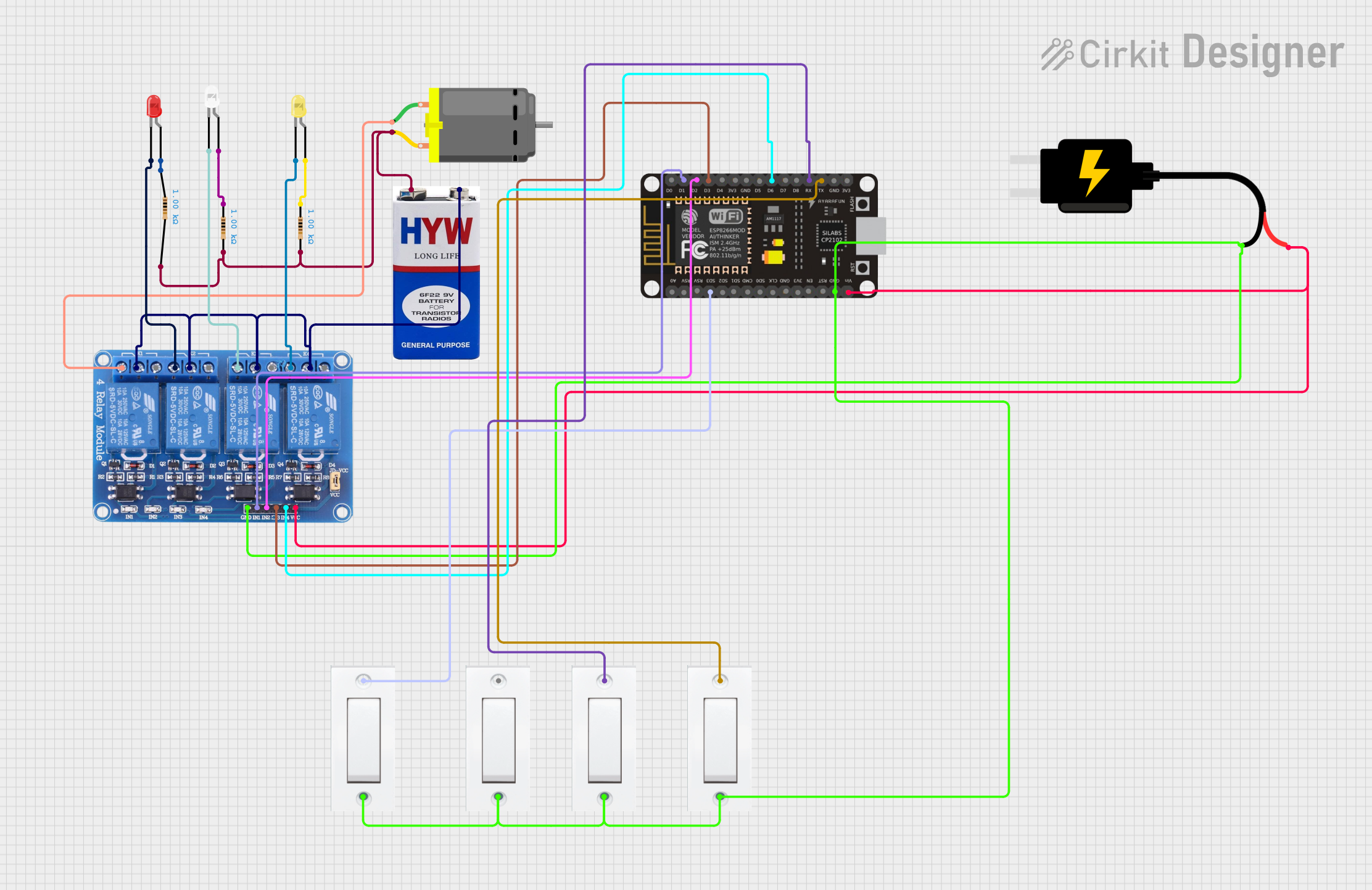
The circuit is designed to control a DC motor and three LEDs (red, white, and yellow) using an ESP8266 NodeMCU microcontroller and a 4-channel 5V relay module. The ESP8266 NodeMCU is interfaced with the relay module to switch the motor and LEDs on and off. The motor and LEDs are powered by a 9V battery, with resistors in series with the LEDs to limit current. The circuit also includes four flush switches, which are connected to the ESP8266 NodeMCU for additional control inputs. The 5V DC source powers the ESP8266 NodeMCU and the relay module.
Component List
- ESP8266 NodeMCU: A microcontroller board with WiFi capability, used for controlling the relays and reading the state of the flush switches.
- Relay 4 Channel 5V: A relay module with four channels, used to control the power to the DC motor and the LEDs.
- DC Motor: A motor that operates on direct current, controlled by one of the relays.
- LED (Red, White, Yellow): Light-emitting diodes of different colors, each controlled by a relay channel.
- Resistor (1k Ohms): Three resistors with a resistance of 1000 Ohms, used to limit the current through the LEDs.
- 9V Battery: A battery providing the power source for the motor and LEDs.
- DC Source 5V: A power supply providing 5V to the ESP8266 NodeMCU and the relay module.
- Flush Switch: Four switches used to provide input to the ESP8266 NodeMCU.
Wiring Details
ESP8266 NodeMCU
- D1: Connected to Relay IN1
- D2: Connected to Relay IN2
- D3: Connected to Relay IN3
- D6: Connected to Relay IN4
- RX: Connected to Flush Switch VCC
- TX: Connected to Flush Switch VCC
- SD3: Connected to Flush Switch VCC
- GND: Common ground with DC Source 5V, Relay, and all Flush Switches
- VIN: Connected to DC Source 5V VCC
Relay 4 Channel 5V
- IN1 - IN4: Controlled by ESP8266 NodeMCU
- GND: Common ground with ESP8266 NodeMCU, DC Source 5V, and all Flush Switches
- VCC: Connected to DC Source 5V VCC
- COM1 - COM4: Connected to 9V Battery negative terminal
- NC1: Connected to DC Motor pin 1
- NC2: Connected to Red LED cathode
- NC3: Connected to White LED cathode
- NC4: Connected to Yellow LED cathode
DC Motor
- Pin 1: Connected to Relay NC1
- Pin 2: Connected to 9V Battery positive terminal through a 1k Ohm resistor
LED: Two Pin (Red, White, Yellow)
- Cathode: Connected to Relay NC2, NC3, and NC4 respectively
- Anode: Connected to 9V Battery positive terminal through a 1k Ohm resistor for each LED
Resistor (1k Ohms)
- Pin1: Connected to the anode of the respective LED
- Pin2: Connected to the positive terminal of the 9V Battery
9V Battery
- Negative Terminal: Connected to Relay COM1 - COM4
- Positive Terminal: Connected to DC Motor pin 2 and the anodes of the LEDs through the resistors
DC Source 5V
- VCC: Connected to ESP8266 NodeMCU VIN and Relay VCC
- GND: Common ground with ESP8266 NodeMCU, Relay, and all Flush Switches
Flush Switch
- VCC: Connected to ESP8266 NodeMCU RX, TX, and SD3
- GND: Common ground with ESP8266 NodeMCU, DC Source 5V, and Relay
Documented Code
No code has been provided for the ESP8266 NodeMCU. The code would typically include the initialization of the GPIO pins connected to the relay module, the setup of WiFi connectivity, and the logic to read the state of the flush switches and control the relays accordingly.