Arduino Uno R3 Controlled LDR-Based Adaptive LED Lighting
Circuit Documentation
Summary
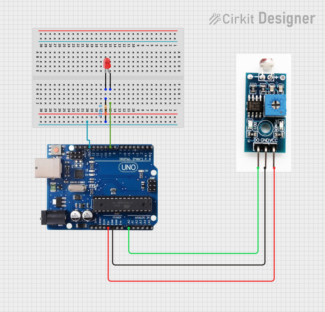
This document provides a detailed overview of a simple light-responsive LED circuit controlled by an Arduino Uno R3 microcontroller. The circuit utilizes a light-dependent resistor (LDR) to measure ambient light levels and adjusts the brightness of a connected LED accordingly. The Arduino Uno R3 reads the analog value from the LDR and outputs a corresponding PWM signal to control the LED's brightness.
Component List
Arduino Uno R3
- Description: A microcontroller board based on the ATmega328P.
- Purpose: Acts as the central processing unit for the circuit, reading sensor data and controlling the LED.
- Pins: USB Port, Power Jack, Not Connected, IOREF, RESET, 3.3V, 5V, GND, VIN, A0-A5, SCL, SDA, AREF, Digital Pins 0-13.
Resistor (220 Ohms)
- Description: A passive two-terminal electrical component that implements electrical resistance as a circuit element.
- Purpose: Limits the current flowing through the LED to prevent damage.
- Properties: Resistance - 220 Ohms.
LED: Two Pin (red)
- Description: A two-pin light-emitting diode.
- Purpose: Emits light when powered, with brightness controlled by the Arduino.
- Pins: Anode, Cathode.
LDR Sensor
- Description: A light-dependent resistor whose resistance varies with the ambient light level.
- Purpose: Senses the ambient light level to control the LED brightness.
- Pins: DO (Data Output), GND (Ground), VCC (Power Supply).
Wiring Details
Arduino Uno R3
- Digital Pin 9: Connected to the anode of the LED.
- GND Pin: Connected to one pin of the Resistor and the GND pin of the LDR sensor.
- 5V Pin: Provides power to the VCC pin of the LDR sensor.
- Analog Pin A0: Receives the analog signal from the DO pin of the LDR sensor.
Resistor (220 Ohms)
- One Pin: Connected to the GND pin of the Arduino Uno R3.
- Other Pin: Connected to the cathode of the LED.
LED: Two Pin (red)
- Anode: Connected to Digital Pin 9 of the Arduino Uno R3.
- Cathode: Connected to one pin of the Resistor.
LDR Sensor
- VCC Pin: Connected to the 5V pin of the Arduino Uno R3.
- GND Pin: Connected to the GND pin of the Arduino Uno R3.
- DO Pin: Connected to Analog Pin A0 of the Arduino Uno R3.
Documented Code
// Declare variables for pin numbers
int ldrPin = A0;   // Analog pin connected to LDR
int ledPin = 9;    // Digital pin connected to LED

void setup() {
  pinMode(ledPin, OUTPUT);  // Set LED pin as output
  Serial.begin(9600);       // Start serial communication
}

void loop() {
  int ldrValue = analogRead(ldrPin); // Read the light level from LDR

  // Print the light level to the Serial Monitor
  Serial.print("LDR Value: ");
  Serial.println(ldrValue);

  // Map the LDR value to an LED brightness value (0 to 255)
  int ledBrightness = map(ldrValue, 0, 1023, 0, 255);

  // Set the LED brightness based on LDR value
  analogWrite(ledPin, ledBrightness);

  // Add some delay before the next reading
  delay(500);
}
Filename: sketch.ino
Description: This Arduino sketch reads the analog value from the LDR sensor connected to pin A0 and maps this value to a range suitable for LED brightness control (0-255). It then outputs this value as a PWM signal to pin 9, which is connected to the LED. The Serial Monitor outputs the raw LDR value for debugging purposes. The loop includes a 500ms delay between readings.