ESP32-Based Multi-Sensor Robotic Controller with Motor Actuation
Circuit Documentation
Summary
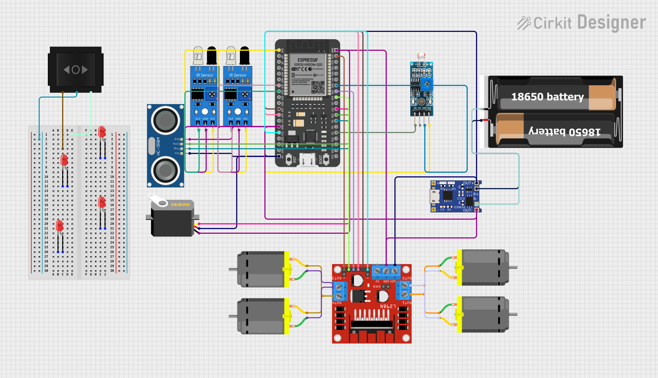
This circuit integrates various components controlled by an ESP32 microcontroller to perform a range of functions. The ESP32 manages input from sensors, drives servo and DC motors, and controls the state of LEDs. An ultrasonic sensor provides distance measurements, while IR sensors detect the presence of objects. The LDR module senses light intensity, and the L298N motor driver interfaces with the DC motors. Power management is handled by a TP4056 module charging a 2x 18650 battery pack. The circuit is designed for applications requiring sensor integration, motor control, and basic power management.
Component List
ESP32 - 38 pins
- Description: A microcontroller with Wi-Fi and Bluetooth capabilities and a variety of GPIO pins.
- Pins: 3V3, EN, SP, SN, G34, G35, G32, G33, G25, G26, G27, G14, G12, GND, G13, SD2, SD3, CMD, 5V, G23, G22, TXD, RXD, G21, G19, G18, G5, G17, G16, G4, G0, G2, G15, SD1, SD0, CLK
Servo
- Description: A motor capable of precise position control.
- Pins: gnd, vcc, pulse
LED: Two Pin (red)
- Description: A basic red LED for indication purposes.
- Pins: cathode, anode
HC-SR04 Ultrasonic Sensor
- Description: A sensor for measuring distances using ultrasonic waves.
- Pins: VCC, TRIG, ECHO, GND
IR Sensor
- Description: An infrared sensor for object detection.
- Pins: out, gnd, vcc
Module LDR
- Description: A light-dependent resistor module for detecting light intensity.
- Pins: VCC, GND, DO, AO
L298N DC Motor Driver
- Description: A motor driver module capable of driving up to four DC motors.
- Pins: OUT1, OUT2, 12V, GND, 5V, OUT3, OUT4, 5V-ENA-JMP-I, 5V-ENA-JMP-O, +5V-J1, +5V-J2, ENA, IN1, IN2, IN3, IN4, ENB
DC Motor
- Description: A standard DC motor for rotational motion.
- Pins: pin 1, pin 2
Directional Switch
- Description: A switch to control the direction of current flow.
- Pins: Out 2, IN, Out 1
2x 18650 Battery Pack
- Description: A power source consisting of two 18650 batteries.
- Pins: vcc, gnd
TP4056
- Description: A charging module for lithium-ion batteries.
- Pins: OUT-, B-, B+, OUT+, IN-, IN+
Wiring Details
ESP32 - 38 pins
- GND connected to common ground.
- 5V connected to 5V power rail.
- 3V3 connected to 3.3V power rail.
- G17 connected to Servo (pulse).
- G32, G33 connected to IR Sensors (out).
- G27, G14, G19, G18 connected to L298N Motor Driver (IN1, IN2, IN3, IN4).
- G13, G23 connected to L298N Motor Driver (ENA, ENB).
- G16 connected to HC-SR04 Ultrasonic Sensor (ECHO).
- G4 connected to HC-SR04 Ultrasonic Sensor (TRIG).
- G2 connected to Module LDR (AO).
Servo
- gnd connected to common ground.
- vcc connected to 5V power rail.
- pulse controlled by ESP32 (G17).
LED: Two Pin (red)
- cathode connected to common ground.
- anode connected to positive voltage rail.
HC-SR04 Ultrasonic Sensor
- VCC connected to 5V power rail.
- TRIG controlled by ESP32 (G4).
- ECHO connected to ESP32 (G16).
- GND connected to common ground.
IR Sensor
- out connected to ESP32 (G32, G33).
- gnd connected to common ground.
- vcc connected to 3.3V power rail.
Module LDR
- VCC connected to 3.3V power rail.
- GND connected to common ground.
- AO connected to ESP32 (G2).
L298N DC Motor Driver
- 12V connected to 5V power rail.
- GND connected to common ground.
- IN1, IN2, IN3, IN4 controlled by ESP32 (G27, G14, G19, G18).
- ENA, ENB controlled by ESP32 (G13, G23).
- OUT1, OUT2, OUT3, OUT4 connected to DC Motors.
DC Motor
- pin 1, pin 2 connected to L298N Motor Driver (OUT1, OUT2, OUT3, OUT4).
Directional Switch
- Out 2, IN, Out 1 not connected in this configuration.
2x 18650 Battery Pack
- vcc connected to TP4056 (B+).
- gnd connected to TP4056 (B-).
TP4056
- OUT-, B- connected to common ground.
- B+, OUT+ connected to 5V power rail.
Documented Code
The code for the ESP32 microcontroller is not provided in the input. However, the code would typically include setup and loop functions, initialization of GPIO pins, and logic to handle sensor readings and motor control based on the wiring details provided above. If the code becomes available, it should be documented here with comments explaining the functionality of each section and how it relates to the connected components.