
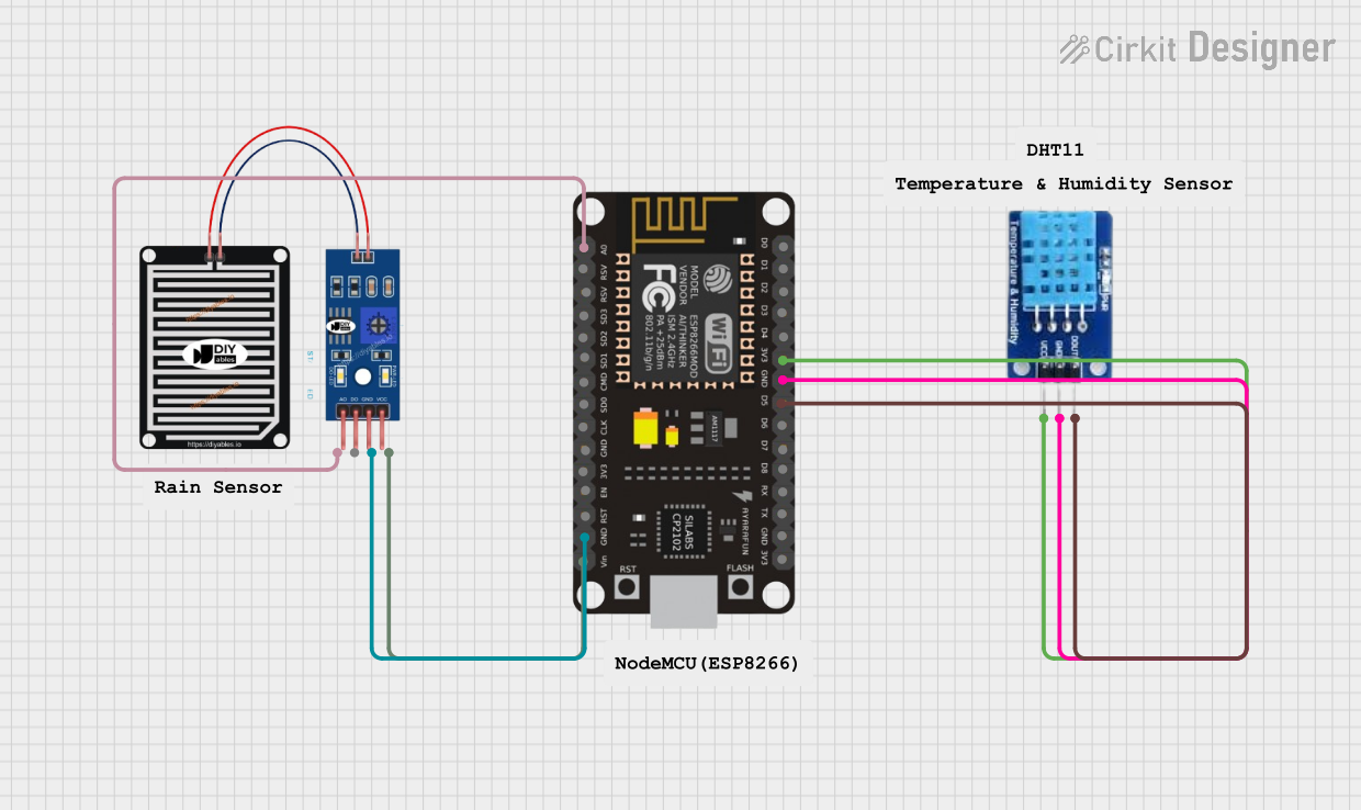
Circuit Documentation
Summary
This circuit integrates a microcontroller (ESP8266 NodeMCU), a temperature and humidity sensor (DHT11), and a rain sensor. The ESP8266 NodeMCU is responsible for reading data from the DHT11 and the rain sensor, processing the information, and potentially taking action based on the sensor readings. The DHT11 provides ambient temperature and humidity data, while the rain sensor can detect the presence of raindrops.
Component List
ESP8266 NodeMCU
- Description: A WiFi-enabled microcontroller module with a wide range of GPIO pins for interfacing with various sensors and devices.
- Pins: D0, D1, D2, D3, D4, 3V3, GND, D5, D6, D7, D8, RX, TX, A0, RSV, SD3, SD2, SD1, CMD, SD0, CLK, EN, RST, VIN
DHT11
- Description: A digital temperature and humidity sensor that provides calibrated digital output.
- Pins: DATA, GND, VCC
Rain Sensor
- Description: A sensor that detects water and can be used to measure rain intensity.
- Pins: AO, DO, GRD, VCC
Wiring Details
ESP8266 NodeMCU
- 3V3 connected to DHT11 VCC
- GND connected to DHT11 GND and Rain Sensor GRD
- D5 connected to DHT11 DATA
- A0 connected to Rain Sensor AO
- VIN connected to Rain Sensor VCC
DHT11
- VCC connected to ESP8266 NodeMCU 3V3
- GND connected to ESP8266 NodeMCU GND
- DATA connected to ESP8266 NodeMCU D5
Rain Sensor
- AO connected to ESP8266 NodeMCU A0
- GRD connected to ESP8266 NodeMCU GND
- VCC connected to ESP8266 NodeMCU VIN
Documented Code
sketch.ino
void setup() {
  // put your setup code here, to run once:

}

void loop() {
  // put your main code here, to run repeatedly:

}
documentation.txt
(No additional documentation provided for the code)
This concludes the documentation for the given circuit. The code provided is a template and needs to be filled in with the logic for initializing the sensors, reading data from them, and performing actions based on the sensor data.