Cirkit Designer
Your all-in-one circuit design IDE
Home /
Project Documentation
Arduino UNO Controlled Robotics Interface with Servo, DC Motor, IR Sensor, and Ultrasonic Sensor

Circuit Documentation
Summary of the Circuit
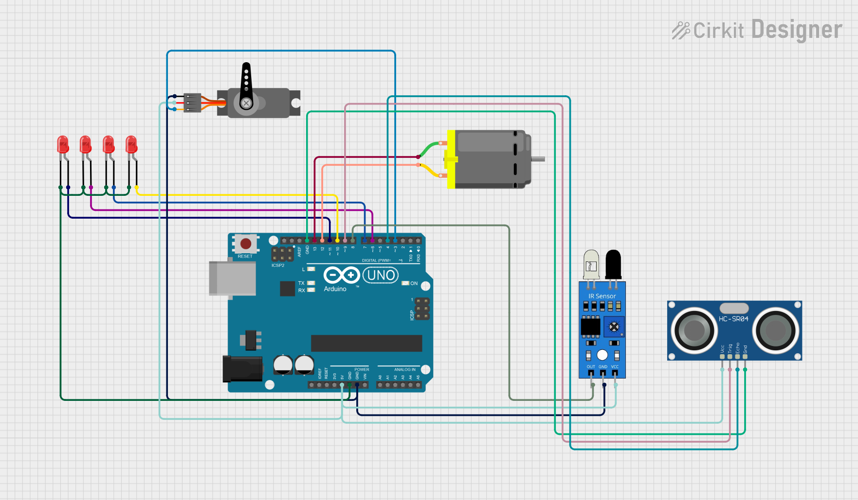
This circuit is designed around an Arduino UNO microcontroller, which serves as the central processing unit for controlling various peripherals including LEDs, a DC motor, a servo motor, an IR sensor, and an HC-SR04 ultrasonic sensor. The circuit is powered by the Arduino UNO's 5V output, which is distributed to the necessary components. Ground connections are also centralized through the Arduino UNO. The microcontroller interfaces with the components through its digital I/O pins, providing control signals to the DC motor, servo, and LEDs, as well as receiving input from the IR sensor and ultrasonic sensor.
Component List
Arduino UNO
- Microcontroller board based on the ATmega328P
- It has 14 digital input/output pins, 6 analog inputs, a 16 MHz quartz crystal, a USB connection, a power jack, an ICSP header, and a reset button.
LEDs: Two Pin (red)
- Simple red LEDs with an anode and cathode for basic light-emitting functionality.
DC Motor
- A basic DC motor with two pins for power and control.
Servo
- A small device that has an output shaft. This shaft can be positioned to specific angular positions by sending the servo a coded signal.
IR Sensor
- An infrared sensor capable of detecting obstacles in its path and providing a digital output.
HC-SR04 Ultrasonic Sensor
- An ultrasonic distance sensor that provides a non-contact distance measurement function.
Wiring Details
Arduino UNO
- 5V pin is connected to the VCC pins of the HC-SR04 Ultrasonic Sensor, IR Sensor, and Servo.
- GND pin is connected to the GND pins of all components.
- Digital pins D13 and D12 are connected to the two pins of the DC Motor.
- Digital pins D11, D10, D7, and D6 are connected to the anodes of individual red LEDs.
- Digital pin D9 is connected to the TRIG pin of the HC-SR04 Ultrasonic Sensor.
- Digital pin D8 is connected to the OUT pin of the IR Sensor.
- Digital pin D4 is connected to the ECHO pin of the HC-SR04 Ultrasonic Sensor.
- Digital pin D3 is connected to the PWM pin of the Servo.
LEDs: Two Pin (red)
- The cathodes of all LEDs are connected to the GND pin of the Arduino UNO.
- The anodes of individual LEDs are connected to digital pins D11, D10, D7, and D6 of the Arduino UNO.
DC Motor
- One pin is connected to digital pin D13 of the Arduino UNO.
- The other pin is connected to digital pin D12 of the Arduino UNO.
Servo
- GND pin is connected to the GND pin of the Arduino UNO.
- VCC pin is connected to the 5V pin of the Arduino UNO.
- PWM pin is connected to digital pin D3 of the Arduino UNO.
IR Sensor
- OUT pin is connected to digital pin D8 of the Arduino UNO.
- GND pin is connected to the GND pin of the Arduino UNO.
- VCC pin is connected to the 5V pin of the Arduino UNO.
HC-SR04 Ultrasonic Sensor
- VCC pin is connected to the 5V pin of the Arduino UNO.
- TRIG pin is connected to digital pin D9 of the Arduino UNO.
- ECHO pin is connected to digital pin D4 of the Arduino UNO.
- GND pin is connected to the GND pin of the Arduino UNO.
Documented Code
Arduino UNO Code (sketch.ino)
void setup() {
  // put your setup code here, to run once:

}

void loop() {
  // put your main code here, to run repeatedly:

}
Additional Notes
- The provided code is a template and does not contain any functional code for controlling the circuit's components. The user is expected to write the necessary code to initialize the pins and implement the control logic for the peripherals based on the specific requirements of the application.