
555 Timer IC and Servo Motor Control Circuit with Adjustable Timing
View and Edit Project In Cirkit Designer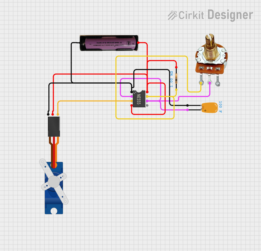
Circuit Documentation
Summary
This circuit involves a 555 Timer IC, a Tantalum Capacitor, a Rotary Potentiometer, a Resistor, a Tower Pro SG90 servo, and a 3.7V power source. The 555 Timer IC is configured to generate a PWM signal to control the servo motor. The potentiometer is used to adjust the frequency of the PWM signal, and the capacitor and resistor are used to set the timing characteristics of the 555 Timer IC.
Component List
555 Timer IC
- Description: A versatile timer IC used for generating precise time delays or oscillation.
- Pins: VCC+, Dis, Th, CV, Rst, Out, Trig, GND
Tantalum Capacitor
- Description: A capacitor with a capacitance of 100 Farads.
- Pins: +, -
PR-Rotary Potentiometer
- Description: A variable resistor used to adjust the frequency of the PWM signal.
- Pins: GND, OUT, VCC
Resistor
- Description: A resistor with a resistance of 1000 Ohms.
- Pins: pin1, pin2
Tower Pro SG90 Servo
- Description: A small servo motor used for precise control of angular position.
- Pins: Signal, +5V, GND
3.7V Power Source
- Description: A power source providing 3.7V.
- Pins: +, -
Wiring Details
555 Timer IC
VCC+ is connected to:
- +5V pin of the Tower Pro SG90 servo
- pin2 of the Resistor
-
- pin of the 3.7V power source
- Rst pin of the 555 Timer IC
Dis is connected to:
- pin1 of the Resistor
- GND pin of the PR-Rotary Potentiometer
Th is connected to:
-
- pin of the Tantalum Capacitor
- Trig pin of the 555 Timer IC
- OUT pin of the PR-Rotary Potentiometer
-
Out is connected to:
- Signal pin of the Tower Pro SG90 servo
GND is connected to:
- GND pin of the Tower Pro SG90 servo
-
- pin of the 3.7V power source
-
- pin of the Tantalum Capacitor
Tantalum Capacitor
+ is connected to:
- Th pin of the 555 Timer IC
- Trig pin of the 555 Timer IC
- OUT pin of the PR-Rotary Potentiometer
- is connected to:
- GND pin of the 555 Timer IC
- GND pin of the Tower Pro SG90 servo
-
- pin of the 3.7V power source
PR-Rotary Potentiometer
GND is connected to:
- pin1 of the Resistor
- Dis pin of the 555 Timer IC
OUT is connected to:
-
- pin of the Tantalum Capacitor
- Th pin of the 555 Timer IC
- Trig pin of the 555 Timer IC
-
VCC is not connected in this circuit.
Resistor
pin1 is connected to:
- Dis pin of the 555 Timer IC
- GND pin of the PR-Rotary Potentiometer
pin2 is connected to:
- +5V pin of the Tower Pro SG90 servo
- VCC+ pin of the 555 Timer IC
-
- pin of the 3.7V power source
- Rst pin of the 555 Timer IC
Tower Pro SG90 Servo
Signal is connected to:
- Out pin of the 555 Timer IC
+5V is connected to:
- pin2 of the Resistor
- VCC+ pin of the 555 Timer IC
-
- pin of the 3.7V power source
- Rst pin of the 555 Timer IC
GND is connected to:
- GND pin of the 555 Timer IC
-
- pin of the 3.7V power source
-
- pin of the Tantalum Capacitor
3.7V Power Source
+ is connected to:
- +5V pin of the Tower Pro SG90 servo
- pin2 of the Resistor
- VCC+ pin of the 555 Timer IC
- Rst pin of the 555 Timer IC
- is connected to:
- GND pin of the 555 Timer IC
- GND pin of the Tower Pro SG90 servo
-
- pin of the Tantalum Capacitor
Code
No microcontroller code is provided for this circuit.