
Arduino UNO-Based GPS and GSM Emergency Alert System with Wi-Fi Connectivity
View and Edit Project In Cirkit Designer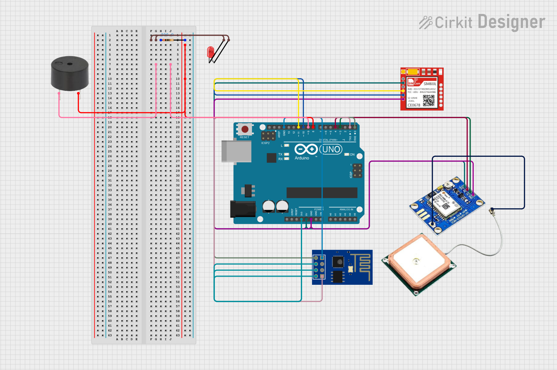
Circuit Documentation
Summary
This circuit integrates an Arduino UNO microcontroller with several modules and components to create a GPS tracking and emergency alert system. The system includes a GSM module (Sim800l) for communication, a GPS module (Ublox NEO-M8N) for location tracking, a WiFi module (ESP8266 ESP-01) for network connectivity, an LED for visual indication, and a buzzer for audible alerts. The Arduino UNO is programmed to read GPS data, send location updates to a server, and trigger emergency alerts via SMS and calls.
Component List
Arduino UNO
- Description: A microcontroller board based on the ATmega328P.
- Pins: UNUSED, IOREF, Reset, 3.3V, 5V, GND, Vin, A0, A1, A2, A3, A4, A5, SCL, SDA, AREF, D13, D12, D11, D10, D9, D8, D7, D6, D5, D4, D3, D2, D1, D0
Sim800l
- Description: A GSM module used for communication via SMS and calls.
- Pins: NET, RST, VCC, RXD, TXD, GND
Ublox NEO-M8N GPS module
- Description: A GPS module used for location tracking.
- Pins: RF coaxial cable connectors, VCC, RX, TX, GND
ESP8266 ESP-01 WiFi Module
- Description: A WiFi module used for network connectivity.
- Pins: TXD, CH_PD, RST, VCC, GND, GPIO_2, GPIO_0, RXD
LED: Two Pin (red)
- Description: A red LED used for visual indication.
- Pins: cathode, anode
Buzzer
- Description: A buzzer used for audible alerts.
- Pins: PIN, GND
Resistor
- Description: A resistor with a resistance of 200 Ohms.
- Pins: pin1, pin2
Wiring Details
Arduino UNO
- 3.3V: Connected to CH_PD, RST, and VCC of ESP8266 ESP-01 WiFi Module
- 5V: Connected to VCC of Ublox NEO-M8N GPS module and Sim800l
- GND: Connected to GND of Ublox NEO-M8N GPS module, Sim800l, and ESP8266 ESP-01 WiFi Module
- D11: Connected to RXD of Sim800l
- D10: Connected to TXD of Sim800l
- D9: Connected to PIN of Buzzer
- D8: Connected to pin2 of Resistor
- D4: Connected to RX of Ublox NEO-M8N GPS module
- D3: Connected to TX of Ublox NEO-M8N GPS module
- D1: Connected to RXD of ESP8266 ESP-01 WiFi Module
- D0: Connected to TXD of ESP8266 ESP-01 WiFi Module
Sim800l
- VCC: Connected to 5V of Arduino UNO
- GND: Connected to GND of Arduino UNO
- RXD: Connected to D11 of Arduino UNO
- TXD: Connected to D10 of Arduino UNO
Ublox NEO-M8N GPS module
- VCC: Connected to 5V of Arduino UNO
- GND: Connected to GND of Arduino UNO
- RX: Connected to D4 of Arduino UNO
- TX: Connected to D3 of Arduino UNO
ESP8266 ESP-01 WiFi Module
- CH_PD: Connected to 3.3V of Arduino UNO
- RST: Connected to 3.3V of Arduino UNO
- VCC: Connected to 3.3V of Arduino UNO
- GND: Connected to GND of Arduino UNO
- RXD: Connected to D1 of Arduino UNO
- TXD: Connected to D0 of Arduino UNO
LED: Two Pin (red)
- cathode: Connected to pin1 of Resistor
- anode: Connected to pin1 of Resistor
Buzzer
- PIN: Connected to D9 of Arduino UNO
- GND: Connected to pin2 of Resistor
Resistor
- pin1: Connected to cathode and anode of LED
- pin2: Connected to D8 of Arduino UNO and GND of Buzzer
Code Documentation
#include <SoftwareSerial.h>
#include <TinyGPS++.h>

// Pin configurations for GSM and GPS modules
SoftwareSerial gsmSerial(10, 11);  // RX, TX for GSM module
SoftwareSerial gpsSerial(3, 4);    // RX, TX for GPS module

TinyGPSPlus gps;

// Pin configuration for emergency button
const int buttonPin = 2;  // Emergency button pin

// Server URL for sending data
const char* serverURL = "https://cuboid-rigorous-red.glitch.me/"; // Replace with your server URL

bool buttonPressed = false;

void setup() {
  pinMode(buttonPin, INPUT_PULLUP);   // Configure button pin as input with pull-up resistor
  gsmSerial.begin(9600);              // Initialize GSM serial communication
  gpsSerial.begin(9600);              // Initialize GPS serial communication
  Serial.begin(9600);                 // Start the serial monitor for debugging

  // Send SMS to confirm system startup
  sendSMS("System started. GPS tracking enabled.");
}

void loop() {
  // Process incoming GPS data
  while (gpsSerial.available() > 0) {
    gps.encode(gpsSerial.read());

    // Check if new GPS location is available
    if (gps.location.isUpdated()) {
      float latitude = gps.location.lat();
      float longitude = gps.location.lng();
      Serial.print("Latitude= "); Serial.print(latitude, 6);
      Serial.print(" Longitude= "); Serial.println(longitude, 6);

      // Send the location to the server
      sendLocationToServer(latitude, longitude);
    }
  }

  // Check if the emergency button is pressed
  if (digitalRead(buttonPin) == LOW) {
    buttonPressed = true;
    delay(200);  // Debounce delay
  }

  if (buttonPressed) {
    // Trigger emergency alert
    sendEmergencyAlert();
    buttonPressed = false;  // Reset button pressed flag
  }
}

// Function to send GPS location to the server
void sendLocationToServer(float lat, float lng) {
  String postData = "lat=" + String(lat, 6) + "&lng=" + String(lng, 6);
  sendHTTPPostRequest("/update-location", postData);
}

// Function to trigger an emergency alert
void sendEmergencyAlert() {
  // Send alert message
  sendSMS("Emergency! Sending location to contacts.");

  // Call predefined contact (example number)
  makeCall("+918454044438");

  // Send alert to server
  String postData = "";
  sendHTTPPostRequest("/alert", postData);
}

// Function to send SMS using GSM module
void sendSMS(String message) {
  gsmSerial.println("AT+CMGF=1");    // Set SMS mode to text
  delay(1000);
  gsmSerial.println("AT+CMGS=\"+918454044438\"");  // Replace with predefined emergency contact
  delay(1000);
  gsmSerial.print(message);
  delay(1000);
  gsmSerial.write(26);  // Send CTRL+Z to indicate the end of the message
  delay(5000);
}

// Function to make a call using GSM module
void makeCall(String phoneNumber) {
  gsmSerial.println("ATD" + phoneNumber + ";");  // Dial the phone number
  delay(10000);  // Wait for 10 seconds
  gsmSerial.println("ATH");  // Hang up the call
}

// Function to send an HTTP POST request to the server
void sendHTTPPostRequest(String endpoint, String postData) {
  gsmSerial.println("AT+CGATT=1");  // Attach to GPRS network
  delay(1000);
  gsmSerial.println("AT+CGDCONT=1,\"IP\",\"your-apn\"");  // Set APN (replace with your APN)
  delay(1000);
  gsmSerial.println("AT+CGACT=1,1");  // Activate GPRS context
  delay(1000);

  gsmSerial.println("AT+HTTPINIT");  // Initialize HTTP service
  delay(1000);
  gsmSerial.println("AT+HTTPPARA=\"URL\",\"" + String(serverURL) + endpoint + "\"");  // Set URL
  delay(1000);
  gsmSerial.println("AT+HTTPPARA=\"CONTENT\",\"application/x-www-form-urlencoded\"");  // Set content type
  delay(1000);
  gsmSerial.println("AT+HTTPDATA=" + String(postData.length()) + ",10000");  // Set data length
  delay(1000);
  gsmSerial.print(postData);  // Send POST data
  delay(1000);
  gsmSerial.println("AT+HTTPACTION=1");