
Arduino UNO Controlled Stepper Motor Elevator with 7-Segment Floor Display
View and Edit Project In Cirkit Designer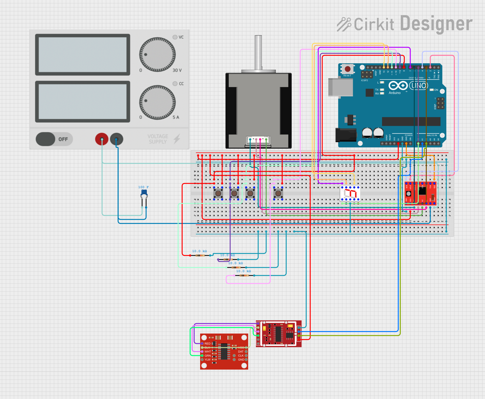
Circuit Documentation
Summary
This circuit is designed to control a stepper motor using an Arduino UNO microcontroller. The stepper motor is intended to move an elevator between four floors, with the current floor number displayed on a 7-segment display. The circuit includes a stepper motor driver to interface the Arduino with the stepper motor, pushbuttons for floor selection, resistors for pull-up configurations, a ceramic capacitor for noise reduction on the motor power supply, and a power supply to drive the motor. Additionally, the circuit integrates an HX711 weighing sensor module with a SparkFun Load Cell Amplifier for potential weight measurement applications.
Component List
Microcontroller
- Arduino UNO: A microcontroller board based on the ATmega328P, featuring digital and analog I/O pins.
Motors
- Nema 17 42-STH48 Stepper Motor: A stepper motor used for precise control of angular or linear position, velocity, and acceleration.
Motor Drivers
- A4988 Stepper Motor Driver (Red): A complete microstepping motor driver with a built-in translator for easy operation.
Power Supply
- Power Supply: Provides the necessary voltage and current to power the circuit components.
Passive Components
- Ceramic Capacitor: A 100 Farad capacitor used to reduce voltage spikes and electrical noise in the power supply.
- Resistors: 10k Ohm resistors used for pull-up configurations on pushbutton inputs.
Input Devices
- Pushbuttons: Used to input user commands for floor selection.
Output Devices
- 7-Segment Display: Displays the current floor number.
Sensors
- SparkFun Load Cell Amplifier - HX711: Amplifies the signals from the load cells.
- HX711 Weighing Sensor Module: Interfaces with the load cells to measure weight.
Wiring Details
Arduino UNO
- Digital Pins:
- D2: Connected to the STEP input of the A4988 Stepper Motor Driver.
- D3, D5, D6, D7, D12, D13, A0: Connected to the segments of the 7-Segment Display.
- D4: Connected to the DIR input of the A4988 Stepper Motor Driver.
- D8, D9, D10, D11: Connected to pushbuttons with pull-up resistors.
- A1, A2: Connected to the HX711 Weighing Sensor Module for data and clock inputs.
- Power Pins:
- 5V: Powers the HX711 Weighing Sensor Module.
- GND: Common ground for the circuit.
Nema 17 42-STH48 Stepper Motor
- Connected to the A4988 Stepper Motor Driver outputs.
A4988 Stepper Motor Driver (Red)
- ENABLE: Connected to GND (Arduino UNO) to enable the driver.
- VMOT: Connected to the positive terminal of the Power Supply through a Ceramic Capacitor.
- GND: Connected to the negative terminal of the Power Supply and common ground.
- 1A, 1B, 2A, 2B: Connected to the corresponding wires of the Nema 17 Stepper Motor.
- STEP: Connected to D2 (Arduino UNO) for step control.
- DIR: Connected to D4 (Arduino UNO) for direction control.
Power Supply
- +: Connected to VMOT of the A4988 Stepper Motor Driver and one terminal of the Ceramic Capacitor.
- -: Connected to GND of the A4988 Stepper Motor Driver and the other terminal of the Ceramic Capacitor.
Ceramic Capacitor
- Connected across the power supply terminals of the A4988 Stepper Motor Driver to stabilize voltage and reduce noise.
Pushbuttons
- Pin 1 (in): Connected to digital pins D8, D9, D10, D11 (Arduino UNO) through 10k Ohm resistors.
- Pin 3 (out): Connected to VDD of the A4988 Stepper Motor Driver.
Resistors
- 10k Ohm resistors connected between pushbuttons and digital pins D8, D9, D10, D11 (Arduino UNO) for pull-up configurations.
7-Segment Display
- Segments connected to digital pins D3, D5, D6, D7, D12, D13, A0 (Arduino UNO).
- Common cathode connected to GND.
SparkFun Load Cell Amplifier - HX711
- GRN, WHT, BLK, RED: Connected to the corresponding pins on the HX711 Weighing Sensor Module.
HX711 Weighing Sensor Module
- VCC: Powered by 5V (Arduino UNO).
- GND: Connected to common ground.
- DO/RX: Connected to A1 (Arduino UNO) for data output.
- CK/TX: Connected to A2 (Arduino UNO) for clock input.
Documented Code
/*
 * Four Floors Elevator Project
 * This code controls a stepper motor to move an elevator to different floors
 * based on button presses. The current floor number is displayed on a 7-segment
 * display.
 */

// Pin definitions
const int dirPin = 4;
const int stepPin = 2;
const int buttonPins[] = {8, 9, 10, 11};
const int segmentPins[] = {3, 5, 6, 7, 12, 13, A0};
const int stepsPerRevolution = 200;
const int stepsPerFloor = 50; // Adjust based on your setup

void setup() {
  pinMode(dirPin, OUTPUT);
  pinMode(stepPin, OUTPUT);
  for (int i = 0; i < 4; i++) {
    pinMode(buttonPins[i], INPUT_PULLUP);
  }
  for (int i = 0; i < 7; i++) {
    pinMode(segmentPins[i], OUTPUT);
  }
  displayFloor(0); // Start at floor 0
}

void loop() {
  for (int i = 0; i < 4; i++) {
    if (digitalRead(buttonPins[i]) == LOW) {
      moveToFloor(i);
      displayFloor(i);
      delay(1000); // Debounce delay
    }
  }
}

void moveToFloor(int floor) {
  int steps = floor * stepsPerFloor;
  digitalWrite(dirPin, HIGH); // Set direction
  for (int i = 0; i < steps; i++) {
    digitalWrite(stepPin, HIGH);
    delayMicroseconds(500);
    digitalWrite(stepPin, LOW);
    delayMicroseconds(500);
  }
}

void displayFloor(int floor) {
  const byte numbers[4][7] = {
    {HIGH, HIGH, HIGH, HIGH, HIGH, HIGH, LOW}, // 0
    {LOW, HIGH, HIGH, LOW, LOW, LOW, LOW}, // 1
    {HIGH, HIGH, LOW, HIGH, HIGH, LOW, HIGH}, // 2
    {HIGH, HIGH, HIGH, HIGH, LOW, LOW, HIGH} // 3
  };
  for (int i = 0; i < 7; i++) {
    digitalWrite(segmentPins[i], numbers[floor][i]);
  }
}
This code is responsible for controlling the stepper motor and displaying the floor number on the 7-segment display based on the button inputs. It initializes the pins, sets up the pull-up resistors for the buttons, and defines the functions for moving to a floor and displaying the floor number.