
Raspberry Pi 5 Controlled Traffic Light System with PWM Servo Driver
View and Edit Project In Cirkit Designer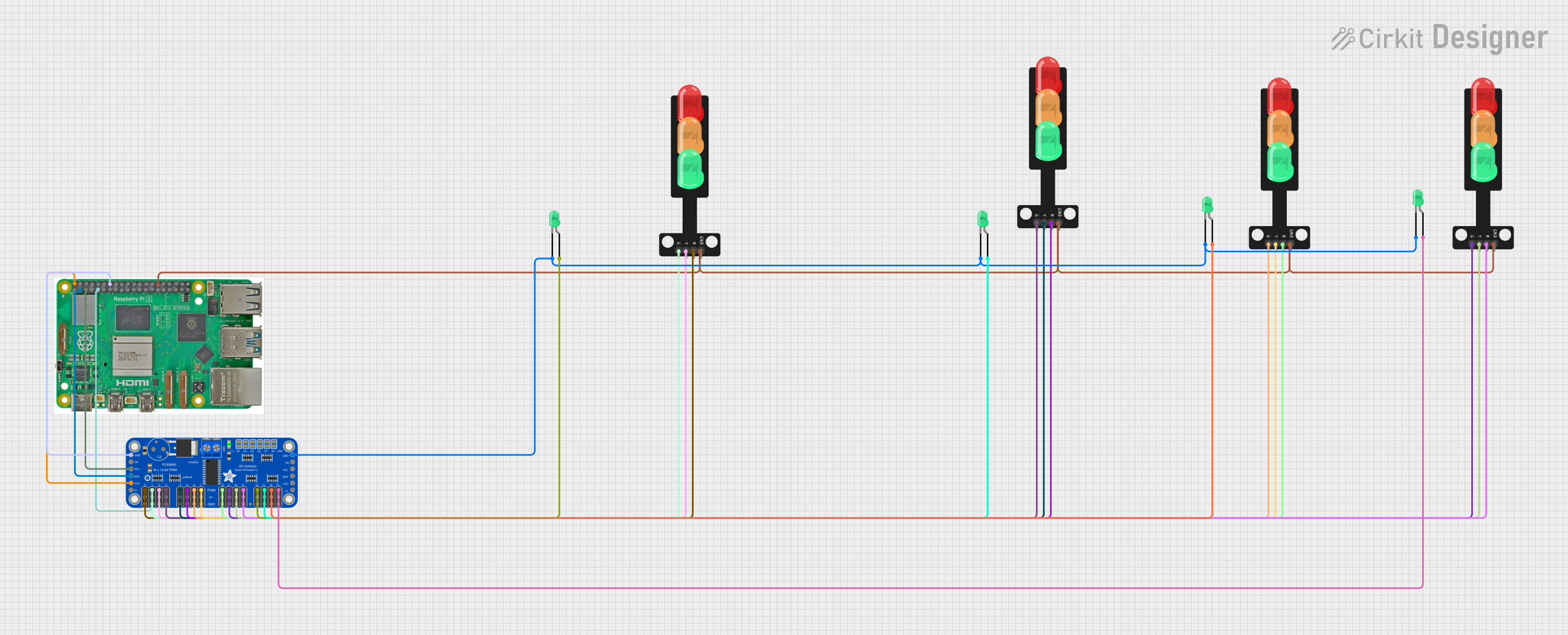
Circuit Documentation
Summary
This circuit is designed to control a series of traffic lights and additional green LEDs using a Raspberry Pi 5 as the central controller and an Adafruit 16-Channel 12-bit PWM Servo Driver for PWM signal generation. The Raspberry Pi communicates with the PWM driver via I2C protocol to control the state of the traffic lights and LEDs. The traffic lights and LEDs are powered by the PWM driver, which in turn is powered by the 5V supply from the Raspberry Pi. Ground connections are shared among all components to complete the circuit.
Component List
Raspberry Pi 5
- Description: A powerful microcomputer with multiple I/O options.
- Pins: Type-C, Micro HDMI, Camera, PoE, Fan, PCIe, USB, Ethernet, 5V, GND, 3.3v, GPIOs.
Adafruit 16-Channel 12-bit PWM Servo Driver - I2C
- Description: A PWM controller for servos or LEDs, interfaced via I2C.
- Pins: 5.0V, VCC, SDA, SCL, OE, GND, PWM0-15, PWRIN.
Traffic Light
- Description: A standard traffic light with Red, Yellow, and Green LEDs.
- Pins: Green, Yellow, Red, GND.
LED: Two Pin (green)
- Description: A simple two-pin green LED.
- Pins: cathode, anode.
Wiring Details
Raspberry Pi 5
- 5V to Adafruit PWM Servo Driver VCC
- GND to Adafruit PWM Servo Driver GND and all Traffic Lights GND
- GPIO 2 (SDA) to Adafruit PWM Servo Driver SDA
- GPIO 3 (SCL) to Adafruit PWM Servo Driver SCL
Adafruit 16-Channel 12-bit PWM Servo Driver - I2C
- VCC from Raspberry Pi 5V
- GND to Raspberry Pi GND, all Traffic Lights GND, and all green LED cathodes
- SDA to Raspberry Pi GPIO 2
- SCL to Raspberry Pi GPIO 3
- PWM0-11 to respective Traffic Light Red, Green, and Yellow pins
- PWM12-15 to respective green LED anodes
Traffic Lights
- Red, Green, Yellow to respective PWM channels on Adafruit PWM Servo Driver
- GND to Raspberry Pi GND
LEDs: Two Pin (green)
- anode to respective PWM channels on Adafruit PWM Servo Driver
- cathode to Adafruit PWM Servo Driver GND
Documented Code
No code has been provided for the microcontrollers in the circuit. The expected code should handle the initialization of the I2C interface on the Raspberry Pi, generate PWM signals to control the traffic lights and LEDs, and implement the logic for traffic light sequencing.
Please note that the actual operation of the circuit will depend on the implementation of the code on the Raspberry Pi, which is responsible for controlling the PWM outputs based on the desired traffic light sequence or pattern.