
Circuit Documentation
Summary
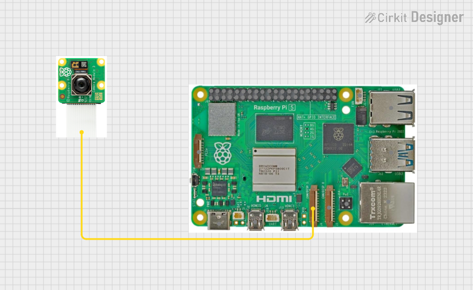
This document provides a detailed overview of a circuit that includes a Raspberry Pi 5 and a Raspberry Pi Camera. The camera is connected to the Raspberry Pi via the Camera 1 pin. This setup is typically used for applications requiring image capture and processing.
Component List
Raspberry Pi 5
- Description: A powerful single-board computer with multiple GPIO pins, USB ports, HDMI ports, and other interfaces.
- Pins:
- Type-C
- Micro HDMI 1
- Micro HDMI 2
- Camera 1
- Camera 2
- PoE
- Fan
- PCIe
- USB 3.0
- USB 2.0
- Ethernet
- 5V
- GND
- 3.3v
- GPIO 14
- GPIO 15
- GPIO 18
- GPIO 23
- GPIO 24
- GPIO 25
- GPIO 8
- GPIO 7
- GPIO 1
- GPIO 12
- GPIO 16
- GPIO 20
- GPIO 21
- GPIO 2
- GPIO 3
- GPIO 4
- GPIO 17
- GPIO 27
- GPIO 22
- GPIO 10
- GPIO 9
- GPIO 11
- GPIO 0
- GPIO 5
- GPIO 6
- GPIO 13
- GPIO 19
- GPIO 26
Raspberry Pi Camera
- Description: A camera module designed to interface with the Raspberry Pi for capturing images and video.
- Pins:
- Signal
Wiring Details
Raspberry Pi 5
- Camera 1: Connected to Raspberry Pi Camera (Signal)
Raspberry Pi Camera
- Signal: Connected to Raspberry Pi 5 (Camera 1)
Code
No code is provided for this circuit.
This document provides a comprehensive overview of the components and their connections within the circuit. The Raspberry Pi 5 serves as the main processing unit, while the Raspberry Pi Camera is used for capturing images or video. The wiring details ensure that the camera is correctly interfaced with the Raspberry Pi.