
Circuit Documentation
Summary of the Circuit
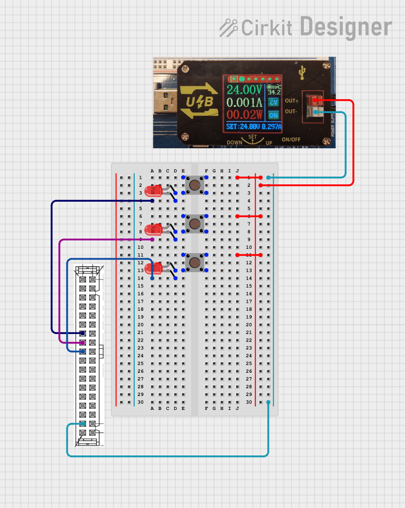
The circuit described by the provided inputs consists of a USB power converter, a 40-pin connector, three pushbuttons, and three LEDs. The USB power converter supplies power to the pushbuttons, which in turn control the LEDs. Each pushbutton is connected to an LED, and when the button is pressed, the corresponding LED is illuminated. The 40-pin connector serves as an interface for the pushbuttons and LEDs, providing common ground and input connections.
Component List
USB Power Converter
- Description: Converts USB power to a suitable voltage and current for the circuit.
- Pins:
+ (Out): Positive voltage output- (Out): Ground output
40-pin Connector
- Description: Provides multiple connection points for inputs and outputs.
- Pins:
0V for output 5D-20DCom for input 5c-20CGeneral purpose input (GP-IN) 0throughGP-IN 15General purpose output (GP-Out) 0throughGP-Out 1524V for output 5D-20DDo not use
Pushbutton
- Description: A momentary pushbutton switch used to control the state of an LED.
- Pins:
Pin 1 (in): Input from power sourcePin 2 (in): Not used in this circuitPin 3 (out): Not used in this circuitPin 4 (out): Output to LED anode
LED: Two Pin (red)
- Description: A red LED that lights up when powered.
- Pins:
cathode: Connected to ground or commonanode: Connected to pushbutton output
Wiring Details
USB Power Converter
+ (Out)connected to thePin 1 (in)of all Pushbuttons.- (Out)connected toCom for input 5c-20Con the 40-pin Connector.
40-pin Connector
Com for input 5c-20Cserves as the common ground for the circuit.GP-IN 6,GP-IN 7, andGP-IN 8are connected to the cathodes of the three LEDs.
Pushbutton
Pin 1 (in)connected to+ (Out)of the USB Power Converter.Pin 4 (out)connected to theanodeof the corresponding LED.
LED: Two Pin (red)
cathodeconnected toGP-IN 6,GP-IN 7, orGP-IN 8on the 40-pin Connector, depending on the specific LED.anodeconnected toPin 4 (out)of the corresponding Pushbutton.
Documented Code
No code has been provided for any microcontrollers in the circuit. If code is added at a later date, it should be documented in this section.