
ESP32-Controlled Autonomous Vehicle with Ultrasonic Sensors and GPS
View and Edit Project In Cirkit Designer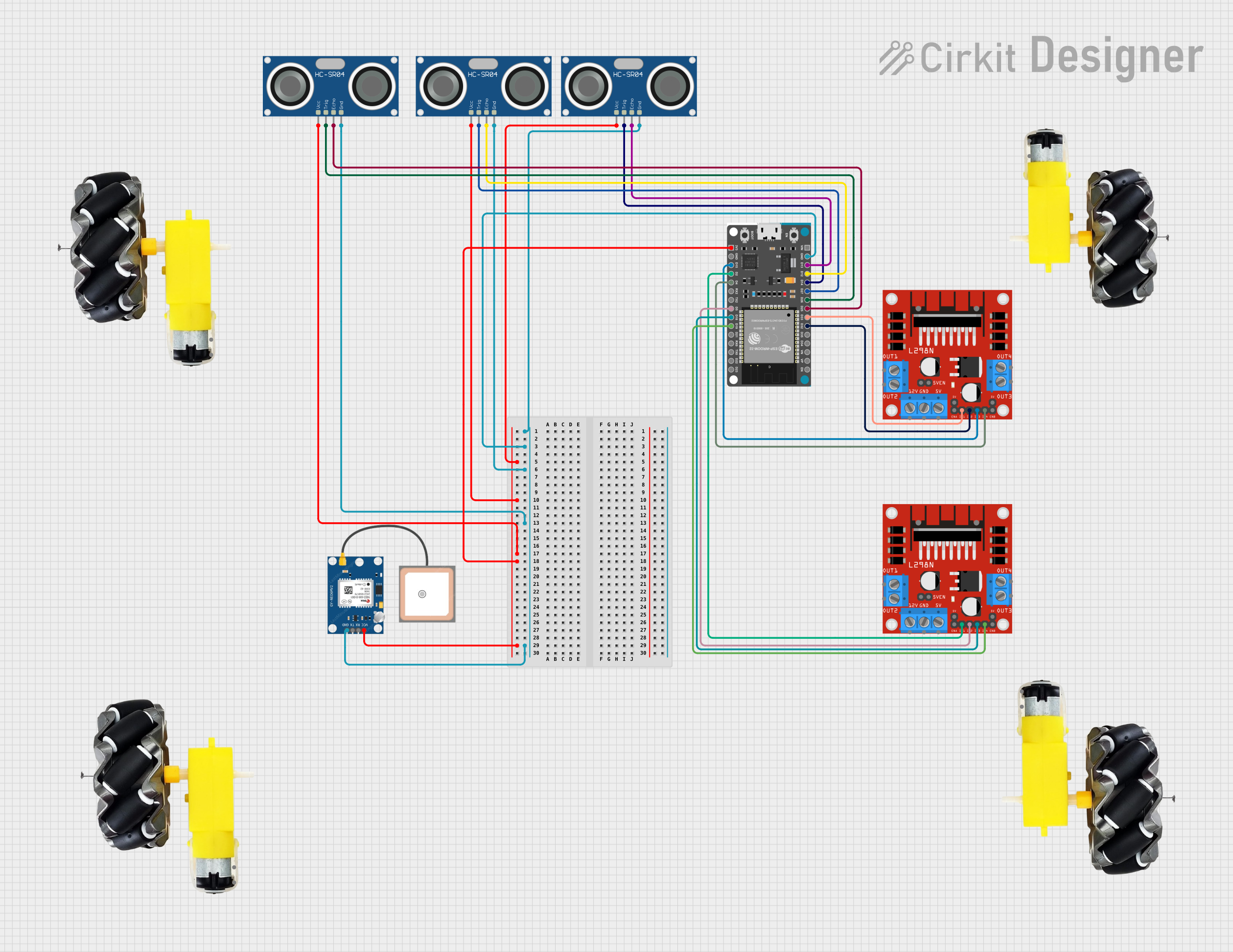
Circuit Documentation
Summary
This circuit integrates multiple components to create a system capable of motor control, distance measurement, and GPS tracking. It uses an ESP32 Devkit V1 microcontroller as the central processing unit to manage inputs and outputs, including driving motors via two L298N DC motor drivers, reading distance measurements from three HC-SR04 Ultrasonic Sensors, and receiving GPS data from a GPS NEO 6M module. The circuit is designed for applications that require precise movement control, location tracking, and obstacle detection, such as robotics or automated vehicles.
Component List
ESP32 Devkit V1
- Description: A microcontroller development board based on the ESP32 chip, featuring Wi-Fi and Bluetooth connectivity.
- Pins: 3V3, GND, D15, D2, D4, RX2, TX2, D5, D18, D19, D21, RX0, TX0, D22, D23, EN, VP, VN, D34, D35, D32, D33, D25, D26, D27, D14, D12, D13, VIN
HC-SR04 Ultrasonic Sensor
- Description: An ultrasonic distance sensor capable of measuring distances by emitting ultrasonic waves and measuring the time taken for the echo to return.
- Pins: VCC, TRIG, ECHO, GND
L298N DC Motor Driver
- Description: A dual H-bridge motor driver module that can drive two DC motors or one stepper motor.
- Pins: OUT1, OUT2, 12V, GND, 5V, OUT3, OUT4, 5V-ENA-JMP-I, 5V-ENA-JMP-O, +5V-J1, +5V-J2, ENA, IN1, IN2, IN3, IN4, ENB
Motor and Wheels
- Description: A set of motors with attached wheels, used for propelling a vehicle or robot.
- Pins: vcc, GND
GPS NEO 6M
- Description: A GPS module capable of providing accurate geographical location data.
- Pins: VCC, RX, TX, GND
Wiring Details
ESP32 Devkit V1
- GND connected to:
- All HC-SR04 Ultrasonic Sensors' GND pins
- GPS NEO 6M GND pin
- 3V3 connected to:
- All HC-SR04 Ultrasonic Sensors' VCC pins
- GPS NEO 6M VCC pin
- D15 connected to L298N DC motor driver IN3
- D2 connected to L298N DC motor driver IN1
- D4 connected to L298N DC motor driver IN4
- D5 connected to L298N DC motor driver IN2
- D18 connected to L298N DC motor driver IN3
- D19 connected to L298N DC motor driver IN4
- D32 connected to L298N DC motor driver IN2
- D33 connected to L298N DC motor driver IN1
- D25 connected to HC-SR04 Ultrasonic Sensor ECHO
- D26 connected to HC-SR04 Ultrasonic Sensor TRIG
- D27 connected to HC-SR04 Ultrasonic Sensor TRIG
- D14 connected to HC-SR04 Ultrasonic Sensor TRIG
- D12 connected to HC-SR04 Ultrasonic Sensor ECHO
- D13 connected to HC-SR04 Ultrasonic Sensor ECHO
HC-SR04 Ultrasonic Sensors
- VCC connected to ESP32 Devkit V1 3V3
- GND connected to ESP32 Devkit V1 GND
- TRIG connected to ESP32 Devkit V1 pins D26, D27, D14 (one sensor per pin)
- ECHO connected to ESP32 Devkit V1 pins D25, D12, D13 (one sensor per pin)
L298N DC Motor Drivers
- IN1, IN2, IN3, IN4 connected to ESP32 Devkit V1 pins D2, D5, D15, D4 for one driver and D33, D32, D18, D19 for the other driver
Motors and Wheels
- vcc and GND pins are assumed to be connected to the corresponding OUT pins of the L298N DC motor drivers, but the exact wiring details are not provided.
GPS NEO 6M
- VCC connected to ESP32 Devkit V1 3V3
- GND connected to ESP32 Devkit V1 GND
- RX and TX pins are not connected in the provided net list.
Documented Code
No code was provided for the microcontrollers in the circuit. The code would typically include initialization and control of the GPIO pins for communication with the ultrasonic sensors, motor drivers, and GPS module, as well as the main application logic for processing sensor data and controlling motor movement.